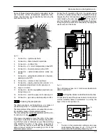
Temperature probe
26
D
F
B
Fig. 9.4
Страница 1: ...odels G C Appl No Activ A 12OV Activ A 15OV Activ A 20OV Activ A 25OV Leave this manual adjacent to the gas meter Warning Service repairs must be carried out only by a qualified Gas Safety Registered...
Страница 2: ...tion 18 7 2 Normaly information 18 7 3 Info modality 19 7 4 Function modes setting modality 19 7 5 Removal of the control panel electr p c b 19 8 Gas valve 21 8 1 Function 21 8 2 Description of the pa...
Страница 3: ...Ighition electrodes Burner Fan Air box air gas mixer Pipe silencer Electronic control box Condensate trap C h pressure relief valve Condensing heat purger valve Control panel Gas valve Gas restrictor...
Страница 4: ...e boiler Pull the lower part of the front panel and lift it upwards Fig 2 3 C C Fig 2 3 To remove the side panels loosen the screws B Fig 2 2 and C Fig 2 3 Pull the side panels towards the outside To...
Страница 5: ...ted into main electronic p c b box proceed as follows 1 Remove the front panel of the case Terminal block lid removal 2 To remove the terminal block lid E Fig 2 7 free the front hooks E Fig 2 7 3 Slig...
Страница 6: ...ht panels of the boiler 3 Open the drain tap F Fig 2 10 until the boiler is completely emptied F CLOSED OPEN Fig 2 10 4 To help the draining of the primary circuit loose the condensing heat exchanger...
Страница 7: ...h flow temp probe NTC probe Condensate trap bu bn bu bn og vt bu bn bk bk rd rd bu gnye bn ye vt bn brown bu blue bk black wh white rd red og gy grey gn green ye yellow vt violet og orange gnye green...
Страница 8: ...Diagrams 6 3 2 Circuit voltages 230 Electrical voltages with burner on during c h operation 230 Safety thermostat 0 Fan Supply network 230 C h external 230 Gas valve pump...
Страница 9: ...Boiler settings Control panel electr p c b Gas valve C h flow temp probe C h return temp probe Fan air restrictor Ignition electrode Detection electrode Safety thermostat Gas restrictor Flue temp prob...
Страница 10: ...ty valve when the boiler is off J J J Lock out is indicated as Er on the display Note Useful information can be obtained also from the optical indication given by the appliance display see section 4 1...
Страница 11: ...tted Er 09 Faulty flue temperature probe NTC Er 10 RESET Lockout flue temperature probe NTC Flue temperature 120 C Er 14 RESET Faulty pump absence of water flow in the main circuit or primary temperat...
Страница 12: ...els see section 2 3 Disconnect the flue system from the boiler 4 Disconnect the air manifold D Fig 5 4 by pulling it 5 Disconnect the rubber pipe E Fig 5 2 6 Unscrew the gas connectors F 7 Remove gas...
Страница 13: ...24 Remove the Condensing heat exchanger slightly move it upwards turn it frontwards freeing it from the below screws X Fig 5 4 Fig 5 2 and then extract it forwards 25 Reassemble the Condensing heat e...
Страница 14: ...ted and supplies the fan regu lating its speed The Main electronic control ignition p c b has a safety function and any incorrect interventions or tampering can result in conditions of dangerous funct...
Страница 15: ...is converted into an elec tric signal by means of temperature probes The user setting the desired temperature with the con trol panel p c b key If the power requested is lower than 40 of the maxi mum...
Страница 16: ...ollowing table gives details of each parameter and the possible value that can be set Important at the end of the setting operation it is im portant to fill update the table in the installation manual...
Страница 17: ...Pr 27 25 45 factory set 25 C Tab 6 1 6 5 Checks n Check that the fuses are complete If the Main electronic control ignition p c b does not supply any device pump fan etc check that the fuses 10 Fig 6...
Страница 18: ...s in the reverse order Important When re assembling the Main electronic control igni tion p c b 7 It is not necessary to utilise static protections but it is advisable to ensure that the pcb is handle...
Страница 19: ...exact NO YES Is flue temperature higher than 110 C YES NO beginning of wait period flame presence End of wait period YES NO YES starts ignition discharges Opens gas valve beginning of ignition period...
Страница 20: ...be interven lockout Er 14 RESET Faulty pump or primary tempera ture above 105 C Er 15 RESET None or too low water flow Faulty pump temp difference between probes higher than 35 C Er 16 RESET Possible...
Страница 21: ...e INFO mode hold keys A and C Fig 7 1 pressed at the same time The following table gives details of each parameter and the possible value that can be show Description Parameter Value External temperat...
Страница 22: ...screws B 5 Delicately flex the hooks C in the directions indi cated Fig 7 3 in order to release the circuit from the box 6 Remove the Control panel electronic p c b 7 Reassemble the Control panel elec...
Страница 23: ...electricity supply to the boiler switch ing on the fused spur isolation switch 6 Set the boiler in c h function as illustrated in Fig 8 3 C h function Fig 8 3 7 Make sure that the room thermostat is...
Страница 24: ...tion 18 Allow the analyser to give a stable reading 19 Read the CO2 value It should be between Model Type gas CO2 value range Activ A 12OV A ti A 15OV Natural G20 8 2 9 0 Activ A 15OV Propane G31 9 2...
Страница 25: ...he electrical connector 4 Fig 8 2 3 Measure the electrical resistance between the connector pins of the on off operators as illus trated in Fig 8 11 ON OFF Operator approx 920 ON OFF Operator approx 6...
Страница 26: ...d in section 8 3 After any service operation on the components of the gas circuit check all the connections for gas leaks Warning After cleaning or replacement as detailed above it is deemed necessary...
Страница 27: ...ctricity supply before removing any covering or component Disconnect the cable from the Temperature probe Measure the temperature of the pipe C c h flow Tem perature probe Fig 9 3 or of the pipe D c h...
Страница 28: ...Temperature probe 26 D F B Fig 9 4...
Страница 29: ...er pipe C Fig 10 2 4 Unscrew the gas connectors D and remove the gas pipe E 5 Disconnect the connector F 6 Disconnect the fan connector G by pressing the plastic hook placed on the side of the connect...
Страница 30: ...electrodes carrying out the removal operation in reverse or der 11 3 Removal of the burner Warning isolate the boiler from the mains electricity supply before removing any covering or component 1 Remo...
Страница 31: ...Ignition and detection electrodes 29 Ignition electrode 3 5 mm earth electrode Fig 11 4 n Check the connection wires...
Страница 32: ...ntain a tem perature below that of the safety thermostat and no overheat intervention should occur Warning isolate the boiler from the mains electricity supply before removing any covering or componen...
Страница 33: ...covering or component 1 Remove all the case panels 2 Disconnect the connector B from the Flue tem perature probe NTC by pressing the plastic hook placed on the side of the connector 3 Unscrew and rem...
Страница 34: ...e cleanness of the trap 1 Unscrew the screws B and remove the plate C Fig 14 2 B C Fig 14 2 Unscrew the plug D on the bottom of the trap A and re move dirt eventually deposit Fig 14 3 14 3 Removal War...
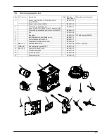
Страница 35: ...Activ A 25OV 1 BI1462 102 3 Fan 1 BI1313 102 4 Gas valve 1 BI1313 103 SIT 848 Sigma 0848135 5 Main Electronic control ignition p c b 1 BI2035 113 6 Control panel electronic p c b 1 BI2035 101 7 Tempe...
Страница 36: ...1796220170 17962 2017 0 1710 36A4 UK Biasi UK Ltd Commercial Road Leamore Enterprise Park WALSALL WS2 7NQ Tel 01922 714600 www biasi co uk 29 04 2010 N...