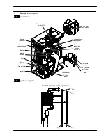


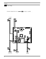


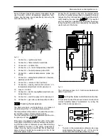


Main electronic control/ignition p.c.b.
15
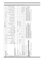
PARAMETER
DIGIT VALUES
Chimney
sweep
function
Pr 09 00
= No chimney
sweep fun (factory
set)
01
= Low power
sweep---test
04
= C.h. power
sweep---test
07
= D.h.w. power
sweep---test
C.h. reignition fre-
quency
Pr 10 00
÷
99
(0÷600 sec.)
(factory set
30
= 3
minutes)
C.h. pump post---cir-
culation
Pr 11 00
÷
99
(0÷600 sec.)
(factory set
10
= 1
minute)
Max. useful output in
c.h. mode
Pr 12 00
÷
99
(0÷100%)
factory set:
99
= Activ A 12OV
99
= Activ A 15OV
99
= Activ A 20OV
99
= Activ A 25OV
C.h. pump working
type
Pr 13 00
= Depends on
room
thermostat
(factory set)
04
= Always running
Ignition power
Pr 14 00
÷
99
(0÷100%)
factory set:
Natural gas (G20)
30
= Activ A 12OV
30
= Activ A 15OV
30
= Activ A 20OV
40
= Activ A 25OV
Propane (G31)
40
= Activ A 12OV
40
= Activ A 15OV
40
= Activ A 20OV
40
= Activ A 25OV
K value (external
probe diagram)
Pr 15 01
(=0,1)÷
60
(=6,0)
K value
factory set:
00
= Off
Not used
Pr 16
D.h.w. burner turn off
function
Pr 17 00
= Burner off at
fixed d.h.w. = 65
˚
C
(factory set)
01
= Brurner off at
set point +5
˚
C
NTC on the c.h. re-
turn
Pr 18 00
= Probe not pres-
ent
(factory set)
01
= Probe present
PARAMETER
DIGIT VALUES
Not used
Pr 19
Not used
Pr 20
Not used
Pr 21
Not used
Pr 22
Not used
Pr 23
Not used
Pr 24
Not used
Pr 25
Not used
Pr 26
C.h. minimum set-
point
Pr 27 25
÷
45
(factory set
25
˚
C)
Tab. 6.1
6.5
Checks
n
Check that the fuses are complete
If the
Main electronic control/ignition p.c.b.
does not
supply any device (pump, fan, etc.) check that the
fuses 10 (Fig. 6.2) are complete.
If a fuse has blown replace it with one that has the same
characteristics after having identified the reason for fail-
ure.
n
Lock sequence
Start the boiler until the burner is ignited.
With the burner firing, interrupt the gas supply. The
Main electronic control/ignition p.c.b.
must carry out
four complete ignition cycles and then, after about 4
minutes, goes to lock---out state.
Switch off and on the electricity supply to the boiler, by
means of the fused spur isolation switch, the device
must not unlock and the burner must not turn on
6.6
Removal of the electronic control p.c.b
Warning: isolate the boiler from the mains
electricity supply before removing any
covering or component.
When replacing the
Main electronic control/ignition
p.c.b.
all parameters must be correctly checked /
adjusted accordingly with the values noted in table
in the installation manual see chapter COMMIS-
SIONING section: Setting record (for information on
parameters see also section 6.4).
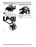
1
Remove all the body panels (see section 2.2).
2
Gain access to the parts located inside
the Main
electronic p.c.b. box
as explained in the section
2.4 of this manual.
3
Remove all the wiring connected to the
Main elec-
tronic control/ignition p.c.b.
.
Содержание Activ A 12OV
Страница 28: ...Temperature probe 26 D F B Fig 9 4...