


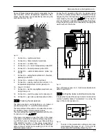


Main electronic control/ignition p.c.b.
14
Fig. 6.5
2
To move through the parameters press c.h. set
keys (A or C Fig. 6.6)
A
C
Fig. 6.6
3
The display shows Fig. 6.7
Fig. 6.7
4
To modify the parameter press contemporary the
keys (A --- B Fig. 6.8)
A
B
Fig. 6.8
5
To change the parameters press c.h. set keys (A
or C Fig. 6.6)
6
To memorize the setting press the key (B Fig. 6.9)
B
Fig. 6.9
7
To exit for setting without modifing the set press
the keys (B --- C Fig. 6.10)
C
B
Fig. 6.10
To reset the boiler to the normal operation press con-
temporary the 3 keys (A --- B --- C Fig. 6.4) for 10 sec-
ond.
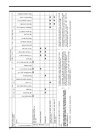
The following table gives details of each parameter and
the possible value that can be set.
Important: at the end of the setting operation it is im-
portant to fill/update the table in the installation
manual see chapter COMMISSIONING section: Set-
ting record.
PARAMETER
DIGIT VALUES
Boiler type (to be up-
dated with the com-
plete range)
Pr 01 00
= No power Er 99
18
= Activ A 12OV
19
= Activ A 15OV
20
= Activ A 20OV
21
= Activ A 25OV
Not used
Pr 02
Not used
Pr 03
Not used
Pr 04
Gas type
Pr 05 00
= G20 Natural
05
= G31 Propane
Not used
Pr 06
C.h. flow max
temperature
˚
C
Pr 07 85
÷
45
(factory set
85
˚
C)
Factory parameters
reset
Pr 08 00
= No reset
04
= All parameters
return to factory set
with the exclusion of
Pr 01 and Pr 05
39
= All parameters
return to factory set
included Pr 01
and Pr 05
Содержание Activ A 12OV
Страница 28: ...Temperature probe 26 D F B Fig 9 4...