
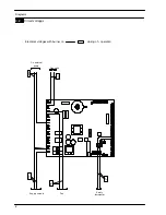


Control panel electronic p.c.b.
19
LCD
FUNCTION
Delayed burner ignition for setting
the system (uu fl tem-
perature flashing)
Boiler in chimney sweep function-
ing mode.
The chimney sweep is activated
by setting “parameter 09=01”
and is visualised by the switching
on of the hand and alternate
flashing between the tempereture
and the communication and radi-
ator symbol.
Thermostat Delayed:
Boiler test performing.
Useful output limitation (temp. dif-
ference between probes higher
than 25
˚
C):
Boiler test performing.
Flame detection error (An flasch-
ing + error flashing number)
7.3
Info modality
The INFO mode allows the display of some information
on the boiler functioning status. In case of malfunction-
ing of the boiler, it may be useful to communicate such
information to the Authorised Service Centre Engineer
so that the causes can be understood.
In order to access the INFO mode, press keys A and C
(Fig. 7.1) at the same time until the letter
di
appears on
the display that alternates with a code (Fig. 7.2).
Fig. 7.2
To scroll the values press B (reduce) and A (increase).
keys (Fig. 7.1). In order to exit the INFO mode, hold
keys A and C (Fig. 7.1) pressed at the same time.
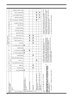
The following table gives details of each parameter and
the possible value that can be show.
Description
Parameter Value
External temperature
˚
C
(if fitted)
d1
--5
K value (external probe dia-
gram) (the value is x 10)
d2
12
Offset (Transaltion of K diagram
± 15
˚
C)
d3
--10
C.h. temperature
˚
C (calcu-
lated by external sensor)
d4
66
C.h. flow temperature
˚
C
d5
78
C.h. return temperature
˚
C
d6
44
Flue temperature
˚
C
d8
67
Fan speedy (the value has to
be x 100 = 4400 rpm)
d9
44
SW version BC (burner control)
dc
01
SW version MB (main board)
dd
03
Tab. 7.1
7.4
Function modes setting
modality
It is possible to select the various boiler control function
modes hereafter named “parameters” by using the
keys of the control panel p.c.b.
During the function modes setting, the boiler does not
operate.
To get in function modes setting modality see section
6.4
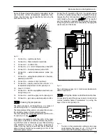
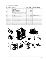
7.5
Removal of the control panel electronic
p.c.b
Warning: isolate the boiler from the mains
electricity supply before removing any
covering or component.
1
Remove all the body panels (see section 2.2).
2
Gain access to the parts located inside
the
Con-
trol panel electronic p.c.b.
as explained in the
section 2.3 of this manual.
3
Remove all the wiring
A
connected to the
Control
panel electronic p.c.b.
(Fig. 7.3).
Содержание Activ A 12OV
Страница 28: ...Temperature probe 26 D F B Fig 9 4...