


32
14
Condensate trap
14.1
Function
The condensate trap
A
in Fig. 14.1 and Fig. 14.3 allows
the discharge of the condensate via the condensate
drain pipe avoiding in the mean time the escape of
combustion products.
A plastic ball closes the trap outlet in case that the trap
is empty.
A
Fig. 14.1
If the drain pipe becomes blocked, or condensate can-
not drain, the condensate level it the trap rises until it re-
aches the screw attached to the flame detection elec-
trode, this will cause the boiler lock---out.
14.2
Check the cleanness of the trap
1
Unscrew the screws
B
and remove the plate
C
(Fig. 14.2).
B
C
Fig. 14.2
Unscrew the plug
D
on the bottom of the trap
A
and re-
move dirt eventually deposit (Fig. 14.3).
14.3
Removal
Warning: isolate the boiler from the mains
electricity supply before removing any
covering or component.
1
Remove the front and right case panels.
2
Unscrew the screws B and remove the plate C
(Fig. 14.2)
3
Unscrew the threaded locking ring
E
and remove
the flexible pipe
F
(Fig. 14.3).
4
Disconnect the electric connector
G
(Fig. 14.3 ---
Fig. 14.4)
F
H
A
D
E
G
G
Fig. 14.3
5
Remove the forks
H
and remove the condensate
trap
A
moving it downwards (Fig. 14.3).
G
Fig. 14.4
6
Reassemble carrying out the removal operations
in reverse order.
Содержание Activ A 12OV
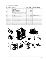
Страница 28: ...Temperature probe 26 D F B Fig 9 4...