


10
5
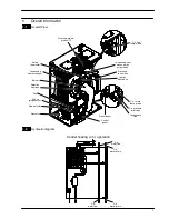
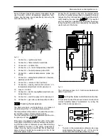
Condensing heat exchanger
5.1
Function
The Condensing heat exchanger
A
in Fig. 5.1 has the
function of transferring heat produced from combus-
tion of the gas and from the flue exhausted gas to the
water circulating in it.
A
B
C
Fig. 5.1
By reducing the combustion products temperature, the
latent heat of the vapour is transferred to the water cir-
cuit, allowing an extra gain of useful heat.
The condensed vapour is then drained through the
condensate trap
B
and the draining pipe
C
.
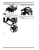
5.2
Removal
Warning: isolate the boiler from the mains
electricity supply before removing any
covering or component.
1
Turn off the gas supply.
2
Remove all the case panels (see section 2).
3
Disconnect the flue system from the boiler.
4
Disconnect the air manifold
D
(Fig. 5.4) by pulling
it.
5
Disconnect the rubber pipe
E
(Fig. 5.2).
6
Unscrew the gas connectors
F
.
7
Remove gas pipe
G
.
8
Unscrew the screws and remove the detection
electrode connector
H
.
9
Unscrew the screws and remove the ignition elec-
trodes connector
I
.
10
Unscrew the screw and remove the overheat
thermostat
J
.
11
Disconnect the connector
K
by pressing the plas-
tic hook placed on the side of the connector.
12
Disconnect the connector
L
J
I
H
K
E
F
G
L
Y
N
S
X
N
Y
F
Fig. 5.2
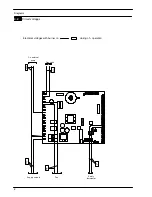
13
Disconnect the fan connector
M
by pressing the
plastic hook placed on the side of the connector
(Fig. 5.4).
O
P
Fig. 5.3
14
Empty the primary circuit of the boiler.
15
Remove the forks
N
(Fig. 5.2).
16
Loosen the connection
O
and remove the pipe
P
(Fig. 5.3) from the Condensing heat exchanger.
Содержание Activ A 12OV
Страница 28: ...Temperature probe 26 D F B Fig 9 4...