


12
6
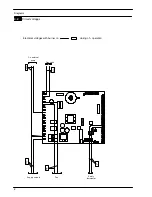
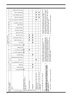
Main electronic control/ignition
p.c.b.
6.1
Function
From other boiler devices....
C.h. flow temperature probe NTC
C.h. return temperature probe NTC
Flue temperature probe NTC
Safety thermostat
Flame detection electrode
Room thermostat (if fitted)
Time switch (if fitted)
On the
Main electronic control/ignition
p.c.b.
......
Function control
C.h. temperature adjustment
Boiler reset button
(printed circuit board p.c.b.)
Inlet Information
External Pump
Gas valve
Fan
Ignition electrodes
Display indicates “Er”*
*control panel electronic p.c.b.
Outlet command
Fig. 6.1
The fundamental function of the
Main electronic con-
trol/ignition p.c.b.
is that of controlling the boiler in rela-
tion to the external needs (i.e. heating the dwelling) and
operating in order to keep the temperature of the hy-
draulic circuits constant.
This is obviously possible within the useful power and
maximum working temperature limits foreseen.
Generally, the
Main electronic control/ignition p.c.b.
re-
ceives inlet information coming from the boiler (the
sensors) or from the outside (printed circuit board
p.c.b., room thermostat, etc.), processes it and conse-
quently acts with outlet commands on other compo-
nents of the boiler (Fig. 6.1).
The
Main electronic control/ignition p.c.b.
is also a full
sequence ignition device and does a sequence of oper-
ations (ignition cycle) which lead to the ignition of the
gas at the burner
It checks the presence of the flame during the entire
period in which it is activated and supplies the fan regu-
lating its speed.
The
Main electronic control/ignition p.c.b.
has a
safety
function
and any incorrect interventions or tampering
can result in conditions of dangerous functioning of the
boiler.
The
Main electronic control/ignition p.c.b.
can lock the
functioning of the boiler (lock state) and stop its func-
tioning up to the resetting intervention. The lock---out is
signalled on the display of the control panel electronic
p.c.b. and can be reset only by using the boiler reset
button placed on the printed circuit board p.c.b. (see
section 7.1).
Some components which are connected to the device
can activate the lock state. The causes of a lock state
could be:
f
The intervention of the safety thermostat (over-
heat of the primary circuit).
f
The intervention of the flue temperature probe
(overheat of the combustion products).
f
A fault on gas supply.
f
Faulty ignition (faulty ignition electrodes, their wir-
ing or connection).
f
Faulty flame detection (faulty detection electrode,
its wiring or connection).
f
Faulty condensate drainage.
f
Faulty gas valve (faulty on---off operators or not
electrically supplied).
f
Faulty
Main electronic control/ignition p.c.b.
.
Other components like the c.h. temperature probes
NTC switch can temporarily stop the ignition of the
burner but allow its ignition when the cause of the inter-
vention has stopped.
NO TAG and Fig. 6.12 show the sequence of the oper-
ations that are carried out at the start of every ignition
cycle and during normal functioning.
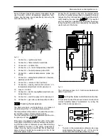
6.2
Selection and adjustment devices
On the
Main electronic control/ignition p.c.b.
several
selection, adjustment and protection devices are lo-
cated. (Fig. 6.2).
Содержание Activ A 12OV
Страница 28: ...Temperature probe 26 D F B Fig 9 4...