INSTALLATION MANUAL
ENGLISH
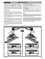
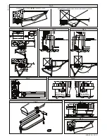
of the gate post is not regular, use expansion bolts with studs so that the
parallel plate of the leaf can be adjusted (fig.4).
• Fasten the gearmotor to the gate post using the 4 screws, pointing the
gearmotor to the left or the right (fig.5).
• Assemble the lever arm as shown in fig.6.
DX= assembly on the right leaf
SX= assemby on the left leaf
Choose the most suitable position of ‘F’ bracket for the fastening to the
leaf.
• Insert the square of the first lever in the output shaft of the gearmotor
and fasten it (fig.7).
• Release the operator by turning the release knob to allow easy movement
of the arm (see paragraph on “EMERGENCY MANOEUVRE”).
• The correct position for the controller arm is shown in fig.8.
The leaf fixing point can be identified by positioning the arm so that it is
in accordance with the distance shown in fig.8.
• Fix the angular towing bar “F” to the leaf by welding or using screws.
• With the controller released, check the correct movement of the arm.
• Repeat the same operation for the other leaf, if installed.
6) ELECTRICAL INSTALLATION SET-UP
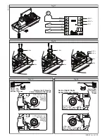
Arrange the electrical installation as shown in fig.10.
The power supply connections must be kept separate from the auxiliary
connections (photocells, sensitive edge, etc.). Fig.10 shows the cross-section
and the number of connections.
WARNING! For connection to the mains, use a multipolar cable with a
minimum of 4x1.5mm
2
cross section and complying with the previou-
sly mentioned regulations. For example, if the cable is out side (in the
open), it has to be at least equal to H07RN-F, but if it is on the inside
(or outside but placed in a plastic cable cannel) it has to be or at least
egual to H05VV-F with section 4x1.5mm
2
.
In fig.11 you will find the junction-box of the operator and the position of the
cable holder which should be fixed with an adequate tightening of the bolt.
In case the motor tours in the opposite side, you should invert the running
buckle “M” of the operator. Refer to the relevant instruction manual for con-
nection of the control panel. Inside the operator the cable must be kept far
from those parts which can be hot.
7) LIMIT-SWITCH SETTING
• Position the limit-switch reference cams “R-FC1” and “R-FC2” as shown
in fig. 12, without tightening the fixing screws.
• Identify the opening and closing limit switches (FC1 and FC2) keeping
in mind that:
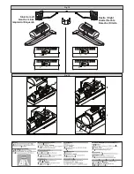
In the left-hand operator (fig. 13):
FC1
corresponds to the
OPENING limit switch
FC2
corresponds to the
CLOSING limit switch
In the right-hand operator (fig. 14):
FC1
corresponds to the
CLOSING limit switch
FC2
corresponds to the
OPENING limit switch
• When the gate is fully closed or opened, rotate the corresponding cam
until you perceive the click of the limit microswitch concerned, and lock
it in position by tightening the appropriate screws as shown in fig. 12.
• Check that the limit switches intervene correctly, initiating a few complete
motor-driven opening and closing cycles.
• Fit the cover on the operator.
• If the control panel is provided with operation-time setting, this must be set
to a value slightly greater than that needed for limit-switch intervention.
• Control the operator through the control board Libra.
8) ADJUSTMENT OF LEAF PHASE DISPLACEMENT
In case of gates with two leaves, the control panel should include a delay
setting function on closing of the second leaf to guarantee a correct closing
manoeuvre. For the wiring of the motor which should close with a slight delay,
refer to the instructions for the control panel installed.
9) MOTOR TORQUE ADJUSTMENT
WARNING: Check that the impact force value measured at the
points established by the EN 12445 standard is lower than that
specified in the EN 12453 standard.
The adjustment of the motor torque (anti-squashing) is performed on the
control panel. See control unit instruction manual.
The adjustment should be set for the minimum force required to carry out
the opening and closing strokes completely observing, however, the limits
of the relevant standards in force.
CAUTION!
Excessive torque adjustment may jeopardise the anti-squash
safety function. On the other hand insufficient torque adjustment may not
guarantee correct opening or closing strokes.
10) EMERGENCY MANOEUVRE (Fig. 15)
In the case of power failure or operation malfunctions, manual emergency
manoeuvre can be carried out by turning the external release knob with
personalised key.
First turn the key clockwise, then rotate the release knob to free the gate.
The knob is to be rotated anticlockwise in the case of a left-hand leaf,
clockwise in the case of a right-hand leaf.
Keep the knob in its release position by turning the key further. Push the leaf
slowly to open or close the gate.
To reactivate motor-driven operation, free the knob from its release position
and bring it back to its initial position for normal operation.
11) AUTOMATION CHECK
Before allowing the automation to be used normally, carry out the following
procedure very carefully:
• Check the correct functioning of all safety devices (limit microswitches,
photocells, sensitive edges etc.).
• Check that the thrust (anti-squash) force of the leaf is within the limits
set by current regulations.
• Check the manual opening command.
• Check the opening and closing operations with the control devices in
use.
• Check the standard and customised electronic functioning logic.
12) AUTOMATION OPERATION
Since the automation can be remote-controlled by means of a remote control
device or a start button, and so out of sight, the good working order of all the
safety devices should be checked regularly. In the event of any anomalous
functioning of the safety devices, consult a specialised technician immediately.
Keep children at a safe distance from the automation operation area.
13) CONTROL
The automation is used for the power-operated opening and closing of the
gate. The control can be of a number of types (manual, remote-controlled,
magnetic badge access control, etc.) depending on requirements and the
characteristics of the installation. See the specific instructions for the various
control systems. Users of the automation must be instructed about its control
and operation.
14) MAINTENANCE
Disconnect the power supply when carrying out any maintenance opera-
tions.
• Lubricate the
IGEA-BT
s of the manoeuvring arm regularly.
• Clean the lenses of the photocells every so often.
• Have a specialised technician (installer) check the adjustment of the
electric clutch.
• In the event of any anomalous functioning which cannot be resolved,
disconnect the power supply and contact a specialised technician (in-
staller). Whilst the automation is out of order, activate the manual release
to allow manual opening and closing.
15) SCRAPPING
WARNING!
This operation should only be carried out by qualified personnel.
Materials must be disposed of in conformity with the current regulations.
In case of scrapping, the automation devices do not entail any particular risks
or danger. In case of materials to be recycled, these should be sorted out by
type (electrical components, copper, aluminium, plastic etc.).
16) DISMANTLING
WARNING!
This operation should only be carried out by qualified person-
nel.
When the automation system is disassembled to be reassembled on another
site, proceed as follows:
• Disconnect the power supply and the entire external electrical installa-
tion.
• In the case where some of the components cannot be removed or are
damaged, they must be replaced.
WARNINGS
Correct controller operation is only ensured when the data contained
in the present manual are observed. The company is not to be held
responsible for any damage resulting from failure to observe the
installation standards
and the instructions contained in the present
manual.
The descriptions and illustrations contained in the present manual are
not binding. The Company reserves the right to make any alterations
deemed appropriate for the technical, manufacturing and commercial
improvement of the product, while leaving the essential product fea-
tures unchanged, at any time and without undertaking to update the
present publication.
12
-
IGEA-BT Ver. 06
D811369_06
Содержание IGEA-BT
Страница 2: ...2 IGEA BT Ver 06 D811369_06...


