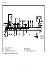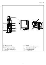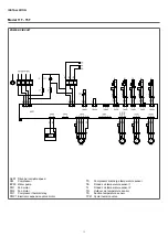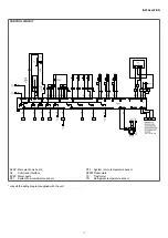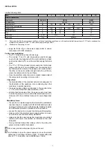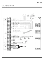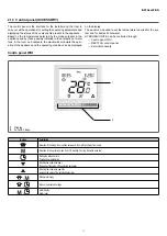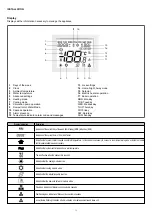
INSTALLATION
40
HYDRONIC UNIT B
40
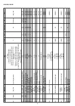
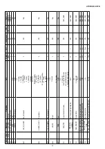
FAUL
T SIGNALS DESCRIPTION
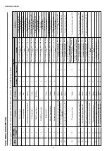
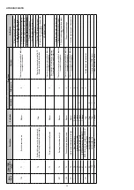
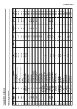
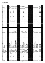
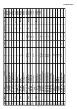
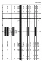
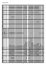
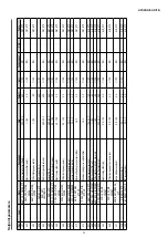
The following tables include lists of alarm signals, their probable cause, ef
fect on the unit and the type of reset.
Alarm Inverter
Alarm [P350] - [P354] or [P360]
- [P364]
Description
Unit status
Reset type
Verifications
Automatic
Feeding cycle
Comment
-
1
EWT
sensor failure
Continue
X
When the operating values return to the correct
range.
1. Check the EWT
sensor (EWT).
2. Check NHC card.
-
2
LWT
sensor failure
Stop
X
When the operating values return to the correct
range.
1. Check the L
WT
sensor (L
WT).
2. Check NHC card.
-
3
Coolant temperature sensor (TR) failure
Stop cpr
X
When the operating values return to the correct
range.
1. Check the
TR sensor (TR).
2. Check NHC card.
-
4
OA
T sensor failure
Continue
X
When the operating values return to the correct
range.
1. Check the auxiliary OA
T sensor (OA
T).
2. Check NHC card.
-
5
DHW_TT
sensor failure
DHW failure
X
When the operating values return to the correct
range.
1. Check the DHW sensor (DHW).
2. Check NHC card.
-
6
CHWSTEMP
sensor failure
X
When the operating values return to the correct
range.
1. Check the CHWSTEMP
sensor
(CHWSTEMP).
2. Check NHC card.
-
7
IA
T sensor failure
Continue
X
When the operating values return to the correct
range.
1. Check the IA
T sensor (IA
T).
2. Check NHC card.
-
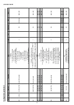
8
Internal IU temperature faults
Continue
X
When the operating values return to the correct
range.
1. Check the internal temperature sensor UI.
2. Check NHC card.
-
9
Replacement sensor failure
Continue
X
When the operating values return to the correct
range.
1. Check the replacement sensor
.
2. Check NHC card.
10
Inverter discharge temperature sensor failure (TD)
Stop cpr
X
This error becomes permanent after 4 attempts
to complete the operation.
1. Check the discharge temperature sensor
(TD).
102
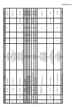
11
Inverter air exchanger temperature sensor
failure(TE)
Stop cpr
X
This error becomes permanent after 4 attempts
to complete the operation.
1. Check the temperature sensor (TE).
103
12
Inverter liquid temperature sensor failure (TL)
Stop cpr
X
This error becomes permanent after 4 attempts
to complete the operation.
1. Check the temperature sensor (TL).
104
13
TO inverter sensor failure
Continue
X
The operation of the unit continues in
emergency mode.
1. Check the outdoor temperature sensor (T
O).
The sensor value is set at 30 ° C in cooling, 10
° C in heating
the emergency mode is canceled when any other value is detected by the
TO sensor
.
108
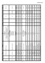
14
Inverter suction temperature sensor failure (TS)
Stop cpr
X
This error becomes permanent after 4 attempts
to complete the operation.
1. Check the suction temperature sensor (TS).
109
15
Inverter heatsink temperature failure
Stop cpr
X
This error becomes permanent after 8 attempts
to complete the operation.
1. Check the correct functioning of the fan
111
16
TE and
TS inverter sensors incorrectly connected
Stop cpr
X
This error becomes permanent after 4 attempts
to complete the operation.
1. Check the temperature sensor (TE,
TS).
-
20
Loss of communication with user interface
Continue
X
When a new message is received from the user
interface
-
21
Communication loss with inverter
Stop cpr
X
When a new message is received from the user
interface
221
22
Communication error between the inverter boards
Stop cpr
X
Simple delay in communication.
-
23
Loss of communication with the slaves
Continue
X
Only the Master unit continues to work.
-
24
Loss of communication with the Master
Stop
X
Содержание 20161618
Страница 1: ...HYDRONICUNITB EN Installer manual...

