INSTALLATION
32
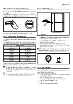
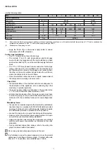
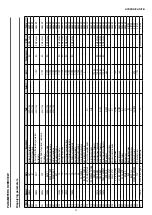
use the following table:
Model
5
7
11
15
11T
15T
Electrical characteristics
Power supply
V/ph/Hz+N
230/1/50
400/3/50
Permitted voltage
V
220 - 240
380 - 415
Total power input
(1)
kW
1,80
3,38
4,73
5,18
10,32
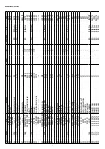
Cos Phi at max. power absorbed
0,98
Full load current
(2)
A
8,90
16,70
23,30
25,60
16,80
Switch magnetermic
A
10
16
25
16
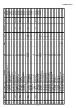
Fuse
A
16
20
32
20
Power cable
n. x mm²
3 x 2,5
3 x 4
5 x 2,5
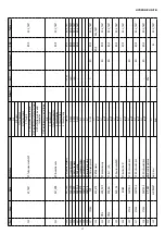
Power cable
Type
H07 RN-F
(1)
Power absorbed by the compressors and fans at the limit operating conditions (i.e. with a saturated inlet temperature of 15 °C and a condensation
temperature equivalent to 68.3 °C) with a rated supply voltage of 400 V
(2)
Maximum unit operating current
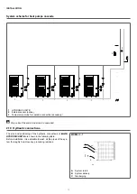
— apply the ferrite ring on the power supply cable to ensure
compliance with EMC standards
Ferrite rings installation:
— The 5 - 7 models do not need ferrite rings.
— The models 11 and 15 with single phase electrical suppy
need a ferrite ring (supplied with the unit) installed on phase
and neutrak cabes (L*N), near the electrical supply therminal
block.
— The 11T e 15T three phases models needs two ferrite rings
(suppy with the unit), one installed near the electrical sup-
ply therminal block around the phases and neutral cables,
the other on the same calbles but just inside the unit frame,
where the cables enter in the unit frame.
— Once the electrical connections are complete, reassemble all
the components operating in reverse order.
Check that:
— the characteristics of the electrical network are adequate for
the absorption of the appliance, also considering any other
machinery in parallel operation
— the power supply voltage corresponds to the nominal value
+/- 10%, with a maximum phase imbalance of 3%
— all disconnection devices from the power supply must have
a contact opening (4 mm) to allow total disconnection in ac-
cordance with the conditions foreseen for overvoltage class
III
Mandatory items:
— the use of an omnipolar magneto-thermal switch, padlockable
line disconnector, compliant with CEI-EN Standards (contact
opening of at least 4 mm), with adequate breaking capacity
and differential protection, installed near the appliance
— connect the device to a properly functioning earthing system
— make sure that the electrical power supply system is compli-
ant with the current national safety standards
— make sure that the power supply line impedance is consistent
with the unit's power consumption, as indicated on the unit's
data plate
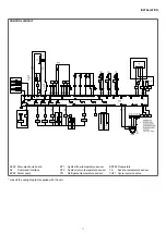
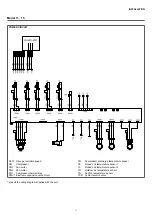
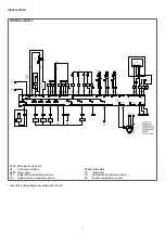
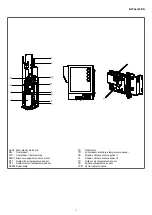
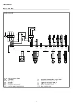
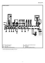
— for any electrical intervention, always refer to the wiring dia-
grams contained within this booklet
0
Do not use gas and water pipes to ground the unit.
0
It is forbidden to pass the power supply and room thermostat
cables near hot surfaces (delivery pipes). If contact with parts
above 50 ° C is possible, use a suitable type of cable.
Содержание 20161618
Страница 1: ...HYDRONICUNITB EN Installer manual...

