153
I20683 - Subject to change.
Wiring Guide
Analog Outputs
III. ANALOG OUTPUTS
III-A. 2 to 10 Volt Analog Output
The controller produces a variable voltage between signal common and the analog output.
The signal common (wire #1) of the actuator must be connected to the signal common of the controller, and the output of the con-
troller is connected to actuator signal input (wire #3).
III-B. Sourcing 4 to 20 mA Analog Output
A sourcing 4 to 20mA analog output sends out a current to the
actuator, and receives it at the signal common terminal.
It is similar to a 0 to 10 V output. The only difference is that
one 500
Ω
resistor has to be installed between wires #3 and
#1 at the actuator. The resistor converts the current (4 to 20
mA) to a 2 to 10 V signal. The resistor should be located at
the actuator.
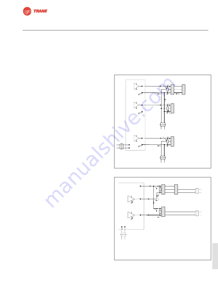
III-C. Sinking 4 to 20 mA Analog Output
A sinking 4 to 20 mA output uses a different logic to create a
control signal. In both a 0 to 10 VDC and sourcing 4 to 20
mA application, the signal is regulated at the positive (+)
source of the signal. In a sinking application the signal is reg-
ulated between the device being controlled and common.
For this reason, the term “Output” in a sinking application is
sometimes confusing.
The controller has one terminal that supplies a constant DC
voltage (often +24V). The input of the actuators (wire #3) are
connected to the constant voltage. A 500
Ω
resistor is con-
nected between wires #1 and #3 on one actuator connected
to each output. (One resistor for each output.) Terminal #1
on the actuator is connected to the output of the controller.
The current will run from the constant voltage on the con-
troller, to wire #3 on the actuator, through the 500
Ω
resistor,
to wire #1, and back to the input of the controller.
From the controllers point of view, all the #3 terminals of the
actuators are at a “common” co24VDC. The signal
common, wire #1, of the actuators will vary with the control
signal.
Because the signal common of the actuators is variable, each
output requires a separate transformer. The signal common
of actuators connected to different outputs must never be
interconnected. (See note ** in the wiring diagram)
Fig III-1
Control Output
Sourcing 4 to 20 mA
L
I
N
E
It is possible to use one
transformer, for actuators
connected to different outputs.
(Connect #1 of one actuator to
minus (COM) on the controller.)
Each transformer needs to be
connected (via wire #1 of one
actuator) to minus (COM) on
the controller.
Only one 500 resistor should
be used for multiple actuators
wired in parallel. Up to four
actuators may be wired in
parallel to the 500
resistor.
*
**
***
(+)
(–)
3
2
1
(+)
(–)
4 to 20 mA
COM
⊥
**
LOAD
RESISTOR
500 , 0.5W
TRANSFORMER
#2
COM
⊥
24 V
A
C
HOT
~
L I N E
+
(+)
(–)
3
2
1
(+)
(–)
4 to 20 mA
LOAD
RESISTOR
500 , 0.5W
TRANSFORMER
#1
COM
⊥
24 V
A
C
HOT
~
L I N E
+
(+)
(–)
3
2
1
(+)
(–)
4 to 20 mA
COM
⊥
OUTPUT 1
LOAD
RESISTOR
500 , 0.5W
+
3
2
1
***
OUTPUT 2
OUTPUT 3
ALWAYS USE A SEPARATE
TRANSFORMER FOR THE
CONTROLLER UNLESS YOU
KNOW A HALF-WAVE
RECTIFIER IS USED!
ACTUATOR
ACTUATOR
ACTUATOR
ACTUATOR
*
Fig. III-2 Sinking 4 to 20 mA
+
HOT ~
24 VAC
COM
⊥
3
2
1
3
2
1
3
2
1
Sinking 4 to 20mA
Controller
POWER
SUPPLY
+ 24V DC
(Typically)
4 to 20 mA
4 to 20 mA
Transformer #1
Transformer #2
*
**
500
500
2 to 10V
+
SINKING
OUTPUT 2
SINKING
OUTPUT 1
(–) (+)
L
I
N
E
L I N E
L
I
N
E
ALWAYS USE A SEPARATE
TRANSFORMER FOR THE
CONTROLLER UNLESS YOU
KNOW A HALF-WAVE
RECTIFIER IS USED!
ACTUATOR
ACTUATOR
ACTUATOR
HOT ~
24 VAC
COM
⊥
It is possible to connect two or more actuators to one transformer,
provided that the actuators are served by the same output.
Each output requires its own transformer.
*
**
(If actuators which are connected to different sinking outputs are
powered, by mistake, from the same transformer, all the actuators
will respond to the average of the output signals. This can be
very deceptive, because when one output signal is changed the
corresponding actuator will move, giving the false impression that
the system works. The problem is that the other actuators will
also move, although they belong to other control loops. For
example: Instead of operating the heating and cooling valves
and dampers in sequence, the valves and dampers will operate
at the same time, which is the wrong control sequence.)
Содержание TRANE TAF Series
Страница 7: ...Notes Work Pad 7 I20683 Subject to change...
Страница 27: ...27 I20683 Subject to change TAF Notes Work Pad...
Страница 57: ...57 I20683 Subject to change TLF Notes Work Pad...
Страница 73: ...73 I20683 Subject to change TTF Notes Work Pad...
Страница 98: ...98 I20683 Subject to change Notes Work Pad...
Страница 165: ...165 I20683 Subject to change Wiring Guide Notes Work Pad...
Страница 166: ...Notes Work Pad 166 I20683 Subject to change...
Страница 167: ...167 I20683 Subject to change Notes Work Pad...


