6 Troubleshooting
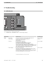
6.1 LED indicators
46
OZD Profi G12D... ATEX 1 V. 03 07/2014
Possible reasons
Signals are received on RS 485 bus cable.
– Bus station is not connected
– Connected bus station is not switched on
– Interruption of one or both wires of the RS 485 bus cable
Sporadic interferences through
– Inadequate sheathing of the RS 485 bus cable
– Open, i.e. RS 485 bus cable connected only on one side to the module
– RS 485 segment not connected or connected only on one side
– Pull/insert a RS 485 bus terminal or terminal plug
Constant interference due to
– Wires A and B of the RS 485 bus cable are swapped
– Short circuit on the RS 485 bus cable
– Transmission timeout caused by a bus station, which is in a bus segment
connected to channel 1
– Module and a bus station connected through channel 1 transmit simulta -
neously (e.g. due to duplicate address allocation or very little set slot time or
when removing the segmentation in the optical line, see chap. 4.1.1, page 20)
– RS 485 driver of the module is defective (e.g. after lightning)
PROFIBUS telegrams are received on the optical channel
Operating mode “Line with fibre optic path monitoring“ and
“redundant optical ring“
Transmission rate is not yet detected - “LED” blinks red
– No transmitting bus station available
– Transmitting and receiving fibre optics are swapped
– No partner module connected or partner module is not switched on
– Connected partner module defective
Transmission rate is detected - LED “system” glows green
– If operating mode “redundant optical ring“ is set, the
optical channel functions as standby channel There is no malfunction in the
OZD Profi or on the fibre optic
– If one of the operating modes “Line fibre optic path monitoring …“ is set, no
PROFIBUS telegrams are received on the optical channel. There is no mal-
function in the OZD Profi or on the fibre optic.
Transmission rate is detected - LED “system” glows green or blinks red/green
– There is no transmitting bus station (fibre optic connection is ok)
– Transmitting and receiving fibre optics are swapped
– No partner module connected or partner module is not switched on
– Connected partner module defective
– Transmission timeout of the connected partner module
– Interruption of a fibre optic cable
– Fibre optic path to partner module is longer than allowed
– Loose connection on a fibre optic connector
– Optical fibre in the fibre optic connector is loose
– If on a redundant optical ring the channel LED glows red even after rectifica-
tion of fibre optic failure, check whether setting of parameter HSA described
in chap. 4.3 page 22 has been complied with.
– Periodically occurring error (see above)
– Loose connection on a fibre optic connector
– Optical fibre in the fibre optic connector is loose
– Only one active bus station is connected, which transmits token only to itself.
After connecting a second station, no error should be displayed
Operating mode “Line without fibre optic path monitoring”
Signals are received on the optical channel
– No transmitting bus station available
– Transmitting and receiving fibre optics are swapped
– No partner module connected or partner module is not switched on
– Connected partner module defective
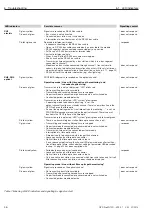
LED indicators
CH1
glows yellow
electric
does not glow
blinks/glows red
CH2, CH3
glows yellow
optical
does not glow
blinks yellow
glows red
blinks red/yellow
glows yellow
does not glow
Signalling contact
does not respond
does not respond
responds
does not respond
does not respond
does not respond
does not respond
responds
responds
does not respond
does not respond
Table 1: Meaning of LED indicators and signalling by signal contact

