A.1 Define reception level of optical channels
57
8 Technical data
OZD Profi G12D... ATEX 1 V. 03 07/2014
A Appendix
A.1 Define reception level of optical channels
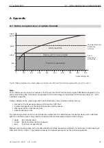
Fig. 33: Relation between the output voltage on the terminals CH2 and CH3 and the signal quality at port 2 or port 3
Normal operation
0
100
200
300
400
500
600
700
800
900
Output voltage [mV]
Signal
quality
good
critical
bad
Optical system reserve reduced
Function not guaranteed
Warning threshold,
defined by
software
Fixed
alarm level
of the relay
Note:
For a valid measuring value it is necessary that the partner-OZD Profi transmits regular PROFIBUS telegrams at the
other end of fibre optic. This can be recognised from the LED image of the partner-OZD Profi (see chap. 6.1, “LED-
indica tors“, page 45).
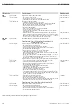
Output voltages on the measuring outlets are influenced by many influence factors like e.g.:
Strength of the transmission power of the partner OZD Profi
Ambient temperature of the optical transmitter and the receiver
Attenuation of the transmission path
Used transmission rate
The measuring outlets are hence not planned as replacement of calibrated level measuring device with calibrated
light. The read-out value is only used for classifying the received optical signal in the 3 classes
good
(Normal operation)
critical
(Optical system reserve reduced)
bad
(Function not guaranteed)
Measurement must be done with a standard floating and high impedance voltmeter. A connection to the housing of
OZD Profi G12D... ATEX 1 is permitted neither by the measuring outputs nor the reference potential.


