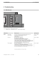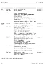
6.1 LED indicators
47
6 Troubleshooting
OZD Profi G12D... ATEX 1 V. 03 07/2014
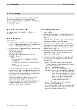
This chapter provides you help to locate the location of
error after error signalling (LED or signal contact).
For this kindly note the description of the LED indicators
in chapter 6.1, pag 45.
6.2 Fault finding
Error display in the system LED
See description of LED indicators in chapter 6.1,
page 45.
Error display on CH1
Check whether
the DIP switch is in the ON position, if the OZD Profi
on the electric star segment is on a star topology. (see
chapter 4.2, “Star topology“, page 21)
the error pattern can be seen even after disconnecting
the electrical bus stations.
Also: device defective”.
Replace the OZD Profi.
No longer exists: The interference is from the
RS485 bus segment.
Check
– the structure and the shielding of the RS485
bus segment
– the RS485 bus segment with a PROFIBUS bus
monitor
– configuration of all bus stations.
* Is not applicable, if the monomaster of a PROFIBUS
network is connected to a RS485 bus segment that is
to be checked In this case replace the conspicuous
OZD profi with another OZD Profi of the network and
subsequently execute the above test.
If the error migrates with the OZD Profi, there is a
defect in the device. Replace the OZD Profi.
If the error does not migrate with the OZD Profi, then
the interference is from the RS485 bus segment.
Execute measures as described above.
Error display on CH2 / CH3
1. Check whether
optically only repeaters of the same type are connect-
ed mutually (see chapter 4, “network topologies”
page 19).
he optical fibre is permitted for the used module type
and the permitted length is not exceeded
optical channels, which are mutually connected, have
the same operating mode set. (see chapter 5.4; “set-
ting the operating mode, connect/disconnect termi-
nating resistors“, page 34)
when connecting and laying the optical bus cables,
specifications in 5.5 “connect optical bus cables”
page 36 were complied with.
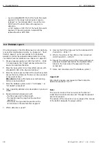
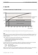
2. Determine the optical reception level (see Appendix
A.1,”determine reception level of the optical chan-
nels“, page 57):
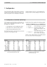
– Level is in the range “Function not guaranteed“.
Check the optical fibre attenuation with an opti-
cal level measuring device.
very high:
Replace optical fibre
within the
One of the two OZD Profi of the
valid range: faulty fibre optic segment is defective.
First replace the other OZD Profi of the
faulty fibre optic segment (i.e. the OZD
Profi, which delivers the transmission -
signal to the above measurement). If
the error persists, instead of this
replace the other OZD Profi.
– Level is in the range “optical system reserve
reduced“ or “normal operation“.
As described above, check the optical reception
level of the other OZD Profi of the faulty fibre optic
segment on the appropriate channel.

