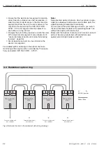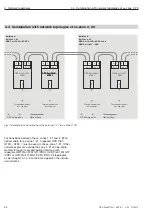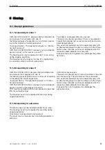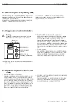
5 Startup
5.5 Connect optical bus cables
36
OZD Profi G12D... ATEX 1 V. 03 07/2014
The repeaters are equipped with two optical ports.
Connect the individual repeaters via a duplex fibre
optic cable with BFOC/2.5 (ST
®
) plug-in connectors.
Note the maximum length of the fibre optic cable and
the possible fibre types specified in the technical
data.
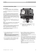
Always ensure that an optical input
a
and an optical
output
J
are conn ected to each other (cross connec-
tion).
Associated BFOC sockets of both the ports are iden-
tified on the lateral adhesive label.
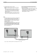
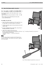
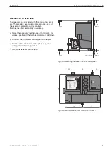
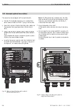
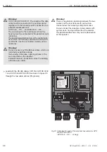
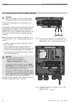
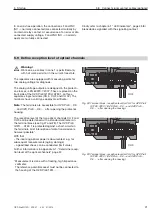
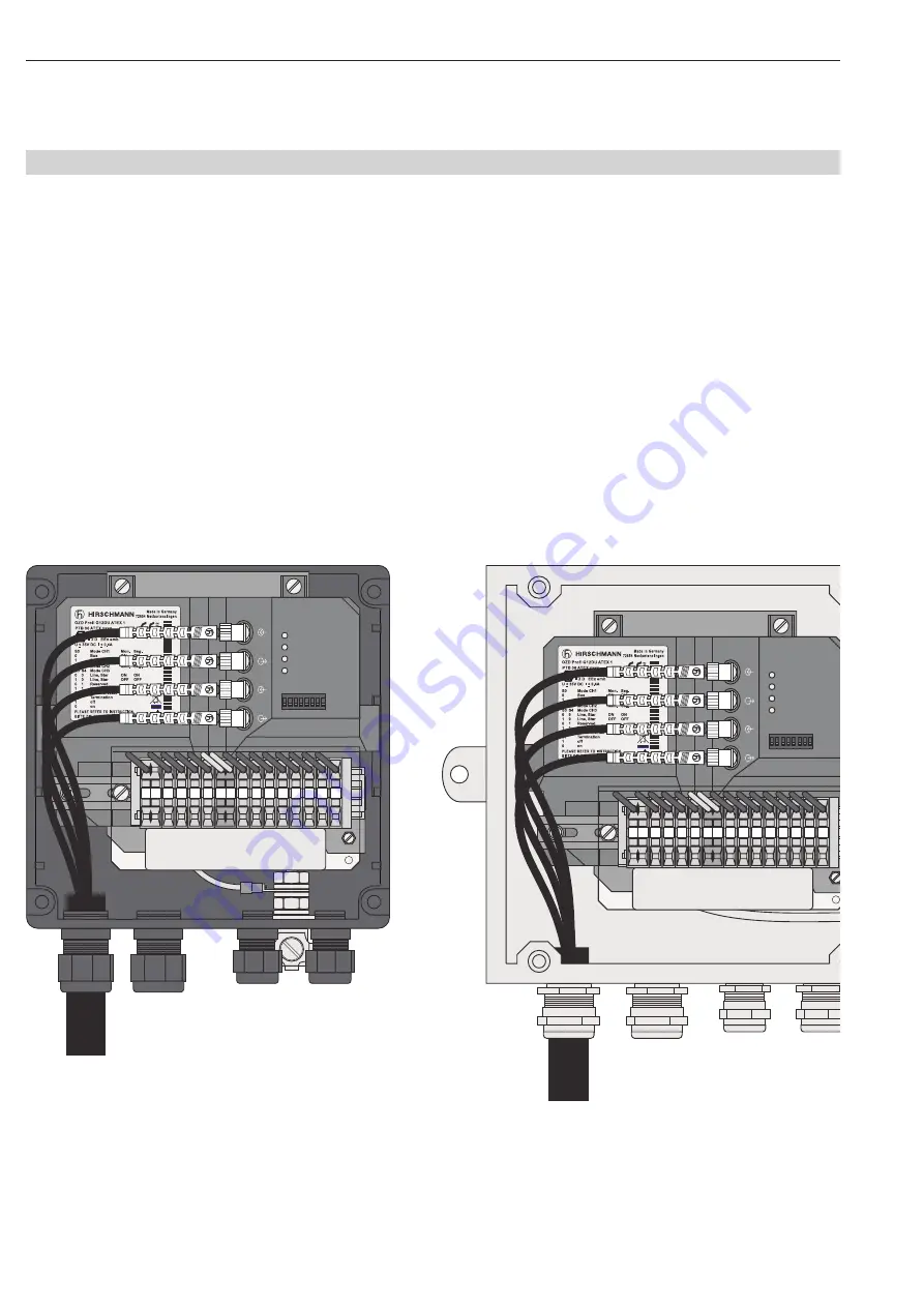
Lead the fibre optic cable for OZD Profi G12DK ATEX 1
and OZD Profi G12DE ATEX 1 as shown in figure 20
and figure 21 via cable entries (PG glands).
Note
: The PG-glands have slotted seals. The fibre
optic connector must not be lead through the seal,
however, you can bend open the seal and lay it
around the fibre optic cable.
Ensure adequate stress relief
of fibre optic cable and note its minimum bending
radii.
Do not close the non-allocated BFOC sockets with
the provided protective caps. Incident am bient light
may interfere with the network, particularly at high
ambient light.
Penetrating dust may make the optical components
unusable.
S0 S1 S2 S3 S4 S5 S6 S7
Sys
te
m
C
H1
C
H
2
C
H
3
C
H
3
C
H
2
24
V*
24
V
DI
B
DI
A
0V
0V
FG FG
DO
B
DO
A
CH
0V
F
NC
F
NO
CH
3
CH
2
F
NICHT UNTER SPANNUNG ÖFFNEN
DO NOT OPEN WHILE ENERGISED
NE PAS OUVRIR SOUS TENSION
NON APRIRE SOTTO TENSIONE
NÃO ABRIR QUANDO ENERGIZADO
94388
1
32
1
00000000
1
S
e
r.
-No
.
: 0
1
23456789
Fig. 20: Cable routing of the fibre optic cable for
OZD Profi G12DK ATEX 1
S0 S1 S2 S3 S4 S5 S6 S7
Sys
te
m
C
H1
C
H
2
C
H
3
C
H
3
C
H
2
24
V*
24
V
DI
B
DI
A
0V
0V
FG FG
DO
B
DO
A
CH
0V
F
NC
F
NO
CH
3
CH
2
F
NICHT UNTER SPANNUNG ÖFFNEN
DO NOT OPEN WHILE ENERGISED
NE PAS OUVRIR SOUS TENSION
NON APRIRE SOTTO TENSIONE
NÃO ABRIR QUANDO ENERGIZADO
94388
1
32
1
00000000
1
S
e
r.
-No
.
: 0
1
23456789
Fig. 21: Cable routing of the fibre optic cable for
OZD Profi G12DK ATEX 1
5.5 Connect optical bus cables

