Section B. Specifications
Belarus-510/512 Operating manual
23
1.1 GB design
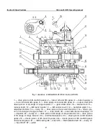
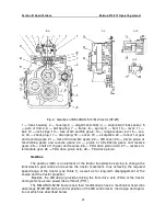
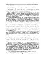
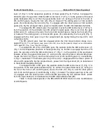
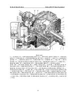
The GB (Fig. 1 and 2) consists of the mechanical gears unit and GB control.
1.1.1 Mechanical gears unit
The mechanical gears unit of the GB consists of the concentric input (31) and out-
put (6) shafts located in the
GB housing (27) (Fig. 1)
*
, as well as an intermediate shaft (29)
parallel to them and the shaft of 1st gear and reverse (24) (Fig. 2).
The input shaft (31) (Fig. 1) is mounted on two ball bearings one of which is placed
in the body (32) on the front wall of the GB housing (27). The second one is in the boring
of the output shaft (6). On the input shaft, a double-wheel drive pinion of 4th and 5th gears
(1) and a drive pinion of 3rd and 6th gears (5) with possibility of axial sliding movement
along the shaft splines are installed.
The output shaft supports (6) (Fig. 1) are two tapered roller bearings, one located in
the GB housing boring (27), and the second in the body (14) installed in the boring of the
rear wall of the GB housing (27). Structurally, the output shaft is made as one piece with
the driven pinion of Ist stage of the range reducer. The gear ring is located cantilevered in
front of the output shaft (6). Between the supports of the output shaft, the driven pinion of
IInd stage of the range reducer (16) is installed fixed on the splines, which is also the drive
pinion of the rear PTO synchronous drive. On the rear arm of the output shaft, the drive
gear (15) of the rear axle final drive (small bevel pinion) is installed fixed on the splines.
On the intermediate shaft (29), fixed on the splines are installed the double-wheel
driven pinion of 5th and 8th gears and reverse gears (26), driven pinion of 4th and 7th
gears (25), and driven pinion of 3rd and 6th gear (24), on the hub of which the double-
wheel intermediate pinion (23) is freely rotating on needle roller bearings, being in constant
mesh with the pinion (22) (Fig. 2) installed on the shaft of 1st gear and reverse gears (24).
On the intermediate shaft (29) (Fig. 1), with the possibility of axial movement the drive pinion (22) of Ist stage
of the range-reducer is installed.
The front support of the intermediate shaft (29) is a ball bearing located in the body
(30) of the front wall of the GB housing (27). The rear support of the intermediate shaft is a
bronze bushing installed in the boring of the drive pinon (21) of IInd stage of the range-
reducer.
The driven pinion of IInd stage of the range-reducer (21) is freely rotating on two
bearings located in the body (20) installed in the boring of the rear wall of the GB housing
(27). The pinion (21) has an inner and outer gear rings, as well as cams located on its rear
end, which serve to synchronously drive the rear PTO. In the boring of the pinion (21), the
seat (18) with bronze bushing is fixed with a pin, which is the rear support of the inner
shaft (17). Outside on the pinion (21), the impeller (19) is fixed, which by intensive spray-
ing improves lubrication of the pinions of the final drive and the rear axle differential of the
tractor.
The 1st gear and reverse shaft (24) (Fig. 2) is installed on two ball bearings located
in the GB housing borings. In the front of the shaft (24) on splines, the sliding pinion (23) of
hill-climbing gears and reverse gears is installed. Backward movement of the sliding pinion
(23) up to meshing with the pinion (25) (Fig. 1) provides forward hill-climbing gears, and
forward movement up to meshing with the intermediate pinion of reverse motion (26) (Fig.
2) provides reverse gears. The intermediate reverse pinion (26) is installed on the axle
(25) and is freely rotating on it on a needle roller bearing. The pinion (26) is in constant
mesh with the smaller gear ring of the double-wheel gear (26) (Fig. 1).
*
Hereinafter, a position designation refers to the figure with the number indicated in paren-
theses immediately after the position designation; if such an indication of the figure is absent, the po-
sition designation refers to the last figure mentioned in the preceding text.

