background image

Control 1.3 Swimming Pool Control Unit 

Operation  

29 

The

 Forced Overflow Channel

 submenu is only available if an overflow pool has been set as the pool type 

(

Treatment 

 Level Control 

 Pool Type

). The filter pump continues to run at normal speed for 

the set time (max. 200 min) after backwashing, regardless of the switching times. 

6.4.3.3 

Pump Type (Setting) 

You need to go to the

 Treatment 

 Pump Type

 submenu to set the pump type used. Here the user can 

choose between the following pump types: 

  Single-phase: corresponds to a 230 V pump 

  Three-phase: corresponds to a 400 V pump 

  Frequency  converter:  the  pump  is  controlled  by  a  frequency  converter  and  can  therefore  be 

operated at different speeds 

  Contactor: pump is connected to an external contactor that is activated by the control unit 

The power supply lines of the single-phase pump, the three-phase pump or the external contactor must be 

connected to the terminals A1. If a frequency converter is used, the pump must be supplied externally with 

continuous voltage. Only the control lines are then connected to the control unit. The following terminals are 

available for connection of the control lines: 

  A13 (speed 2-normal, potential-free N/O contact) 

  A14 (speed 3-increased, potential-free N/O contact) 

  A15 (speed 1-slow, potential-free N/O contact) 

  A16 (stop signal, potential-free switch) 

  A18 (percentage speed, standard signal 0-10 V) 

6.4.3.4 

Frequency Converter Settings 

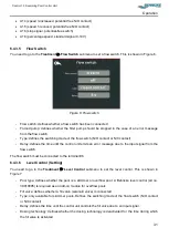
The 

Frequency  Converter  Settings


submenu is only available if “Frequency converter” has been set as 

the pump type

 (

Treatment 

 Pump Type

). 

You need to go to the

 Treatment 

 Frequency Converter 

Settings

 submenu to set the frequency converter used. This is shown in  

Figure 5. The user can set the following frequency converter parameters: 

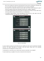
  Frequency converter type: if an external frequency converter (external) or a pump with an integrated 

frequency  converter  is  used.  If  the  pump  has  an  integrated  frequency  converter,  you  can  choose 

between  a  frequency  converter  with  or  without  a  stop  signal.  The  potential-free  terminals  can  be 

switched in different logic depending on the setting. This can be found in table 2. 

  Fault  signal:  defines  whether  the  fault  signal  of  the  frequency  converter  works  as  an  N/C  or  NO 

contact. 

  Speed  X:  the  corresponding  speeds  can  be  specified  in  percentage  values  if  the  integrated 

frequency converter is controlled by means of a standard signal (0-10 V). The values entered here 

are also displayed in the remote portal. 


Содержание Control 1.3

Страница 1: ...Operating Manual Swimming Pool Control Unit BEHNCKE Control 1 3 IMPORTANT READ CAREFULLY BEFORE USE KEEP FOR FUTURE REFERENCE ...

Страница 2: ...varia Michael Haslbeck Straße 13 85640 Putzbrunn Germany Phone 49 0 89 45 69 17 0 Fax 49 0 89 46 85 11 Saxony Anhalt Stötterlinger Straße 36 a 38835 Bühne Germany Phone 49 0 39421 796 0 Fax 49 0 39421 796 30 E mail info behncke com Website www behncke com ...

Страница 3: ...er and Residual Risks 9 Dangers due to Structural Modifications and Spare Parts 10 Safety Measures at the Installation Location 10 Personnel Requirements 11 Responsibility of the Operator 12 Personal Protective Equipment 12 Behaviour in the Case of Danger and Accidents 12 Technical Data 14 Terminal Assignment 14 Measurements and Dimensions 15 Operating Conditions 17 Transport Packaging and Storage...

Страница 4: ...al Menu Navigation 22 Maintenance 40 Safety Instructions for Transport 40 Maintenance Repairs 40 Faults 41 Safety Instructions for Troubleshooting 41 Behaviour in the Case of Faults 41 Error Messages and Faults 41 Spare Parts 44 Ordering Spare Parts 44 Disassembly and Disposal 45 Disassembly 45 Disposal45 Declaration of Conformity 46 Notes 48 Connection Diagrams 49 ...

Страница 5: ...urer provides no warranty and or assumes no liability in the case of incorrect or improper use Check the delivery for completeness and possible damage before setting up the product In addition the applicable local accident prevention regulations and general safety regulations must be observed for the area in which the swimming pool control unit will be used Explanation of Symbols 1 2 1 Warnings Wa...

Страница 6: ...ledge and experience The manufacturer accepts no liability for damage due to Non observance of the operating manual Improper use People not trained to operate the control unit Unauthorised modifications The actual scope of delivery may differ from the explanations and illustrations described here in the case of special versions the use of additional ordering options or due to the latest technical ...

Страница 7: ...scription 1 BEHNCKE Control 1 3 Table 1 System components The swimming pool control unit is used for reading and controlling the following products in swimming pool areas Filter pump Backwash valve Solar pump Solar valve Measurement and control system Fresh water valve Float switch Temperature sensor for outdoor areas Temperature sensor for swimming pool water Chemical level indicator Floor valve ...

Страница 8: ...manuals and the operating instructions of the individual components of the product and the peripherals Adhering to the inspection and maintenance work The control unit must not be operated in environments with a temperature lower than 5 C The control unit must not be installed or operated in an explosive atmosphere The control unit must only be put into operation by specialists The control unit mu...

Страница 9: ...e further chapters of this manual must be observed in order to reduce health risks and to avoid dangerous situations 2 3 1 Electric Current DANGER Risk of fatal injury from electric current Touching live parts poses an immediate risk of fatal injury Damage to the insulation or individual components may prove fatal In the case of damage to the insulation switch off the power supply immediately and ...

Страница 10: ...ons interfere with the operation and may damage the device Cables for the transmission of data and signals must not be laid together with other live cables The device must be disconnected at the backup fuse before opening the terminal box cover Unexpected Start up DANGER Risk of fatal injury from an unexpected start up The BEHNCKE Control 1 3 works as soon as there is voltage at the power input an...

Страница 11: ...making changes to the control unit 2 6 1 Delimitation of the Respective Machine The inspection ends at the control unit housing All other inspections must be made by the commissioning engineer operator user 2 6 2 Electrical Contact There is an increased risk of electric shock due to the humid environment when working on electrical equipment on the system Similarly improper installation of the elec...

Страница 12: ...n particular safety devices Only BEHNCKE spare parts and accessories must be used Any accessories must not endanger the safety of the system Safety Measures at the Installation Location The control unit must be mounted securely on the wall in a control cabinet or on a mounting plate and is not suitable for use in constant sunlight Make sure that the operating temperature of 40 C is not exceeded Op...

Страница 13: ... technical training skills and experience as well as their knowledge of the relevant regulations Qualified electrician Is a person who can assess their assigned work and identify possible dangers because of their technical electrical engineering training skills and experience as well as their knowledge of the relevant standards and regulations Systems mechanic The vocational training of a systems ...

Страница 14: ...ork in order to minimise the health risks Always wear the necessary protective clothing for the respective work when carrying out the work Observe the signs relating to personal protective equipment displayed in the working area Always wear Always wear the following when carrying out any work Protective work clothing Is tight fitting work clothing with low tear strength with tight sleeves and no p...

Страница 15: ...Control 1 3 Swimming Pool Control Unit Safety 13 Alert a doctor and or the fire service Inform the responsible people at the place of use Clear access routes for emergency vehicles ...

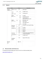
Страница 16: ...l terminals Observe the function of the individual terminals e g input or output signals A faulty connection may destroy the control unit or lead to a malfunction 3 1 1 Inputs Type Name Description Inputs Control 1 3 230 V E1 Badutronic 93 feedback Standard signal E2 Average fill level pH Redox E3 PT1000 E4 Water temperature E5 Collector temperature Digital E6 Flow switch E7 Float switch skimmer E...

Страница 17: ...s 230 V 3 A L2 A7 Backwash valve A8 Rinse valve A9 Fresh water valve A10 Floor valve Potential free N O contact 3 A A11 Release for metering technology A12 Heating A13 Speed 2 A14 Speed 3 A15 Speed 1 Potential free switch 3 A A16 General fault message frequency converter stop signal A17 Collector valve Standard signal A18 Speed of filter pump Module slot A B C D Measurements and Dimensions The fol...

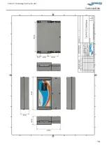
Страница 18: ...Control 1 3 Swimming Pool Control Unit Technical Data 16 ...

Страница 19: ...only be operated under the following conditions If all the wiring has been carried out by a specialist in accordance with the applicable standards The area must be frost proof The area must be covered and dry The area must not have an aggressive atmosphere The area must have a non explosive atmosphere ...

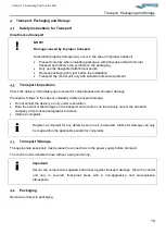
Страница 20: ... and transport damage Proceed as follows in the case of outwardly visible transport damage Do not accept the delivery or only under reservation Note the extent of the damage on the transport documents or on the delivery note of the transport company and produce photographic evidence Initiate a complaint Register a complaint for any defect as soon as it is detected Claims for damage can only be mad...

Страница 21: ...g work must only be carried out by specialists when the control unit is switched off disconnected and has cooled down Installation 5 2 1 Requirements at the Installation Location The foundations and the mounting location must be designed for the anticipated static and dynamic loads The area must be frost proof The area must be covered and dry The area must not have an aggressive atmosphere The are...

Страница 22: ...lled on site in the control unit power supply The main emergency stop switch must be set to off A residual current circuit breaker 30 mA must be installed in the power supply for safety reasons All touching metal parts must be integrated into the equipotential bonding Some of the necessary connections for the individually configured peripheral devices are listed in chapter 6 4 Nevertheless the cir...

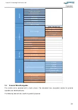
Страница 23: ...maged Otherwise there is a risk of death or injury to the user WARNING Only carry out the maintenance and cleaning work when the system is switched off and disconnected from the power supply DANGER Work on the electrical equipment must only be carried out by qualified electricians Menu Structure The menu structure is divided into four main menus with the respective submenus They are shown in table...

Страница 24: ...witch Level control ECO functions Forced on Forced off Heating Solar mode Sensor calibration Service level Speed 2 Speed 3 Rinsing Solar pump Lowering valve Floor valve Measurement and control technology Chemical fill levels Factory settings Service General Filter cleaning Warming Extras Treatment Freely programmable terminals General Menu Navigation The control unit is operated with a touch scree...

Страница 25: ... user can change the parameters highlighted in grey by tapping on the white arrows If no arrows are provided the user must tap on the parameters highlighted in grey in order to change them The parameter changes made are accepted by tapping on the OK button If you do not tap on the OK button and leave the submenu by tapping on the two arrows next to each other back the old values continue to be val...

Страница 26: ...the date are only displayed if the corresponding peripheral devices and their functions have been selected A grey symbol indicates that the corresponding peripheral device is not currently active The coloured symbol indicates the active status of the peripheral device The colour of the pump symbol also shows the current speed The following symbols are available o Green one wave the pump is running...

Страница 27: ...lance Values The following control unit counters can be queried in the Balance Values submenu If one of the possible peripheral devices is not set up then its balance values are also not displayed Entire filter running time in hours filter Filter running time of the system since the last backwashing in hours filter since filter backwashing Entire running time of the solar heating in hours solar En...

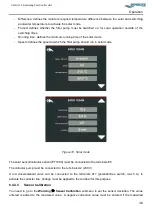
Страница 28: ...apping on a language button 6 4 3 Treatment Settings Menu 6 4 3 1 Switching Times You need to go to the Treatment Switching Times submenu to set the switching times of the filter pump This is shown as a diagram in Figure 2 Please set the parameters in the sequence shown in this operating manual Figure 2 Switching Times submenu In field you choose whether individual switching times or the same swit...

Страница 29: ...y of the week Thursday 16 00 is defined as a switching time in the basic configuration The menu is shown in Figure 3 Figure 3 Backwashing switching times In field you choose the day for which the switching time applies In field you set the time of the individual switching time In field you set the repetition frequency of the individual switching time weekly every 2 weeks every 4 weeks Trigger back...

Страница 30: ...ct the desired pause time here max 200 s to set the pause in order to adjust the rod valve This time also applies for a possible rinse valve Rinsing Setting You need to go to the Treatment Filter Cleaning Rinsing Setting submenu to set the rinsing parameters This has the same layout as the Backwashing Settings submenu Figure 4 In field you select whether a rinse valve 3 way rod valve is connected ...

Страница 31: ...ection of the control lines A13 speed 2 normal potential free N O contact A14 speed 3 increased potential free N O contact A15 speed 1 slow potential free N O contact A16 stop signal potential free switch A18 percentage speed standard signal 0 10 V 6 4 3 4 Frequency Converter Settings The Frequency Converter Settings submenu is only available if Frequency converter has been set as the pump type Tr...

Страница 32: ...nal A16 External Reduced X X Normal X Increased X X Stop Internal with stop Reduced X Normal X Increased X Stop X Internal without stop Reduced X Normal X Increased X Stop If a frequency converter is used the pump must be supplied externally with continuous voltage Only the control lines are then connected to the control unit The following terminals are available for connection of the control line...

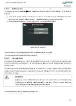
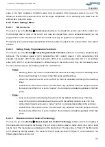
Страница 33: ...he time until the control unit emits an error message due to the input signal from the flow switch The flow switch must be connected to the terminal E6 6 4 3 6 Level Control Setting You need to go to the Treatment Level Control submenu to set the level control This is shown in Figure 7 Pool type defines whether the pool is a skimmer or overflow pool A Behncke level control art no 39019095 is requi...

Страница 34: ...cur when water comes into contact with the hang in electrode HE5 only for overflow pools Forced HE6 defines whether a forced backwashing cycle should occur when water comes into contact with the hang in electrode HE6 only for overflow pools Figure 7 Level control If a level control is required to control the level of an overflow pool this must be connected to the BUS terminals The hang in electrod...

Страница 35: ... output A10 6 4 3 8 Lowering Valve The function of the lowering valve cannot be changed in the control unit The terminal of the lowering valve is only controlled for overflow pools The terminal can be used as a freely programmable terminal for skimmer pools The lowering valve is automatically activated as soon as there is an input signal on the input E8 roller shutter closed The lowering valve is ...

Страница 36: ... to set the auxiliary heating This is shown in Figure 9 The following parameters can be set Sensor defines whether a water sensor is available The heating function can be called up only if a sensor is available If a water sensor is available its temperature values are displayed on the start screen Heating defines whether the heating function should be used to warm up the water temperature Temperat...

Страница 37: ...de This is shown in Figure 10 The following parameters can be set Sensor defines whether a solar sensor is available The solar heating function can be called up only if a sensor is available If a solar sensor is available its temperature values are displayed on the start screen Solar defines whether the solar heating function solar pump and collector should be used to warm up the water temperature...

Страница 38: ...he filter pump should run in solar mode Figure 10 Solar mode The solar sensor collector sensor PT1000 must be connected to the terminals E5 The collector pump must be connected to the terminals A2 230 V A rod valve solenoid valve can be connected to the terminals A17 potential free switch max 3 A to activate the collector line Voltage must be applied to the terminal for this purpose 6 4 4 3 Sensor...

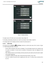
Страница 39: ...minal Timer o Switching times the control unit activates the terminal according to defined switching times that are set identically to the logic of the filter pump switching times o Active the terminal must be set to ACTIVE so that it is activated according to the switching times o Locked when this is set to active the terminal is only activated if the filter pump is active at the same time When t...

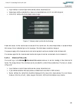
Страница 40: ...urement and control system must be connected to the terminals A5 The release signal for the measurement and control system must be connected to the terminals A11 6 4 5 4 Chemical Fill Levels You need to go to the Extras Chemical Fill Levels submenu to set the reading of the chemical fill levels The empty status of the chemical can be recorded for a total of two substances The menu is shown in Figu...

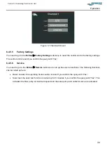
Страница 41: ...onfirm the query with Yes 6 4 5 6 Service You need to go to the Extras Service submenu to call up the service functions The following functions can be called up here Reset counter the operating hours counter is reset if you confirm the query with Yes Solar test the solar test function is called up for 3 minutes if you confirm the query with Yes This activates the filter pump at maximum speed and t...

Страница 42: ...lean Loose components and tools lying around or on top of each other are sources of accidents If components have been removed make sure that they are installed properly Reinstall all fixing elements and observe the screw tightening torques All work must only be carried out by specialists qualified electricians Environmental protection Replaced parts must be disposed of in accordance with the local...

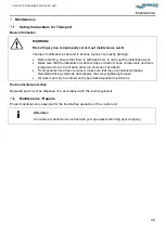
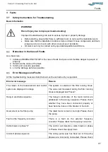
Страница 43: ...far as possible Error Messages and Faults All the troubleshooting measures listed below must be carried out by a specialist Error error message Reason The values of the measurement and control system are displayed in orange The system is outside of the filter running times The value last measured during the filter running times is displayed and frozen Hang in electrode sequence The hang in electro...

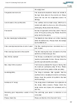
Страница 44: ...due to a lack of water Filter cleaning cancelled on flow switch The filter cleaning has been cancelled on the flow switch due to there being no flow Max fill time reached The fill valve is activated for a bit longer than the maximum permissible fill time Please check the pool for any leaks and the set values Max daily fill time reached The fill valve is activated for longer in the day than the max...

Страница 45: ... parameter X pH chlorine redox is outside of the set limit values The limit values cannot be changed Please check the water values and the measurement control system Communication with hang in electrode extender There is a communication error with the level control Please arrange for a specialist to check the connections Communication with display extender There is a communication error with the l...

Страница 46: ...ety Use only original spare parts supplied by the manufacturer Ordering Spare Parts It is important to specify the following information when ordering spare parts Control unit see type plate Serial no see type plate Year of manufacture see type plate Spare parts orders without the above information cannot be taken into account Obtain spare parts through your authorised dealer or from a specialist ...

Страница 47: ...e power supply caution voltage may still be present after you have disconnected it due to the capacitors Consult a specialist for the disassembly Then disassemble the assemblies and components in accordance with the applicable local environmental regulations Disposal Send the disassembled components for recycling after they have been correctly dismantled Remove and recycle packaging Scrap any left...

Страница 48: ...elektromagnetische Verträglichkeit bezogene Produktnormen DIN EN 61326 1 VDE 0843 20 1 2013 07 Elektrische Mess Steuer Regel und Laborgeräte EMV Anforderungen Teil 1 Allgemeine Anforderungen IEC 61326 1 2012 Deutsche Fassung EN 61326 1 2013 DIN EN 61326 2 2 VDE 0843 20 2 2 2013 08 Elektrische Mess Steuer Regel und Laborgeräte EMV Anforderungen Teil 2 2 Besondere Anforderungen Prüfanordnung Betrieb...

Страница 49: ...ung EN 61000 4 5 2014 DIN EN 61000 4 6 VDE 0847 4 6 2009 12 Elektromagnetische Verträglichkeit EMV Teil 4 6 Prüf und Messverfahren Störfestigkeit gegen leitungsgeführte Störgrößen induziert durch hochfrequente Felder IEC 61000 4 6 2008 Deutsche Fassung EN 61000 4 6 2009 DIN EN 61000 4 11 Ausgabe 2005 02 Elektromagnetische Verträglichkeit EMV Teil 4 11 Prüf und Messverfahren Prüfungen der Störfesti...

Страница 50: ...Control 1 3 Swimming Pool Control Unit Notes 48 Notes ...

Страница 51: ...ol Unit Connection Diagrams 49 Connection Diagrams You will find connection and terminal diagrams to assist you on the following pages You will also find the belonging app if you scan the QR Codes below Link Android App Link iOS App ...

Страница 52: ......

Страница 53: ......

Страница 54: ......

Страница 55: ......

Страница 56: ......

Страница 57: ......

Страница 58: ......

Страница 59: ......

Страница 60: ...H Bavaria Michael Haslbeck Straße 13 85640 Putzbrunn Germany Phone 49 0 89 45 69 17 0 Fax 49 0 89 46 85 11 Saxony Anhalt Stötterlinger Straße 36 a 38835 Bühne Germany Phone 49 0 39421 796 0 Fax 49 0 39421 796 30 E mail info behncke com Website www behncke com ...

Отзывы: