


M-3425 Instruction Book
2–38
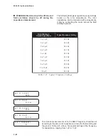
60FL INPUT INITIATE
FL i6 i5 i4 i3 i2 i1
60FL DELAY
________ Cycles
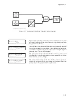
60FL Fuse Loss
Since some functions may inadvertently operate
when a VT fuse is blown, provisions are incorporated
for both internal and external fuse loss detection.
For internal detection of a fuse-loss condition,
positive and negative sequence quantities are
compared. The presence of negative sequence
voltage in the absence of negative sequence current
is considered to be a fuse loss condition. An
additional supervising condition includes a minimum
positive sequence voltage to assure VT inputs are
being applied to the relay.
For the specific application where the above logic
cannot be considered reliable (such as when current
inputs to the relay are not connected, sustained
positive sequence current during fault conditions is
minimal, or negative sequence currents are not
present during fault conditions), provision is made
for ignoring the fuse-loss internal logic by not
highlighting “FL” from among the 60FL Input Initiate
Inputs. Other functions in the relay may be
programmed to be blocked by the fuse-loss detection
logic. Again, in cases where the internal logic is not
considered to be reliable, the FL blocking selection
should not be chosen.
The 60FL function can also be initiated via the
external status inputs, thus accommodating other
fuse loss detection schemes. Any combination (“OR”
logic) of status input (IN1 through IN6) may be used
to initiate operation.
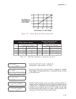
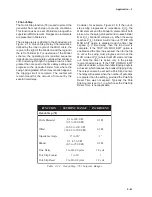
A timer associated with the fuse loss logic is
available. This timer is to assure proper coordination
for conditions which may appear as a fuse loss,
such as secondary VT circuit faults which will be
cleared by local low voltage circuit action. Ranges
and increments are presented in Table 2-19.
N
O
I
T
C
N
U
F
E
G
N
A
R
T
N
I
O
P
T
E
S
T
N
E
M
E
R
C
N
I
)
L
F
0
6
(
n
o
i
t
c
e
t
e
D
s
s
o
L
–
e
s
u
F
T
V
y
a
l
e
D
e
m
i
T
s
e
l
c
y
C
0
6
1
8
o
t
1
e
l
c
y
C
1
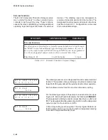
Table 2-19
Fuse Loss (60FL) Setpoint Ranges
The initiating inputs are user-designated. The closing of any of
the externally-connected contacts (across these inputs) will start
the associated time delay to the 60FL function operation. Desig-
nating FL will initiate this function with the internal logic. Exter-
nally initiated fuse loss detection may be input to other status
inputs.
The time delay is set to coordinate for conditions which may ap-
pear as a fuse loss but will be corrected by other protection (such
as a secondary VT circuit fault which will be cleared by local low
voltage circuit action).
Содержание M-3425
Страница 1: ...Instruction Book M 3425 Generator Protection ...
Страница 14: ... 13 M 3425 Generator Protection Relay Figure 1 External Connections ...
Страница 33: ...x M 3425 Instruction Book This Page Left Intentionally Blank ...
Страница 89: ...M 3425 Instruction Book 2 52 This Page Left Intentionally Blank ...
Страница 125: ...1 3 A B C M 3425 Instruction Book 4 26 This Page Left Intentionally Blank ...
Страница 187: ...M 3425 Instruction Book 6 50 This Page Left Intentionally Blank ...
Страница 207: ...M 3425 Instruction Book C 4 This Page Left Intentionally Blank ...
Страница 209: ...D 2 M 3425 Instruction Book Figure D 1 Volts Hz 24 Inverse Curve Family 1 Inverse Square ...
Страница 210: ...Inverse Time Curves Appendix D D 3 Figure D 2 Volts Hz 24 Inverse Family Curve 2 ...
Страница 211: ...D 4 M 3425 Instruction Book Figure D 3 Volts Hz 24IT Inverse Curve Family 3 ...
Страница 212: ...Inverse Time Curves Appendix D D 5 Figure D 4 Volts Hz 24IT Inverse Curve Family 4 ...
Страница 215: ...D 8 M 3425 Instruction Book Figure D 5 Definite Time Overcurrent Curve ...
Страница 216: ...Inverse Time Curves Appendix D D 9 Figure D 6 Inverse Time Overcurrent Curve ...
Страница 217: ...D 10 M 3425 Instruction Book Figure D 7 Very Inverse Time Overcurrent Curve ...
Страница 218: ...Inverse Time Curves Appendix D D 11 Figure D 8 Extremely Inverse Time Overcurrent Curve ...
Страница 223: ...D 16 M 3425 Instruction Book This Page Intentionally Left Blank ...


