


M-3425 Instruction Book
2–16
0-30%
Protection
provided by:
Neutral End of
Generator
Neutral Voltage
0%
50%
Fault Position
(% of stator winding measured
from neutral end of generator)
100%
Terminal End
of Generator
Fundamental (60/50 Hz) neutral
voltage during ground fault
Third-Harmonic (180/150 Hz) neutral
voltage during ground fault
Pre-fault third-harmonic voltage level
5% - 10%
27TN Setpoint
Pre-fault fundamental neutral voltage level
59N Setpoint (typically 5V)
59N
27TN
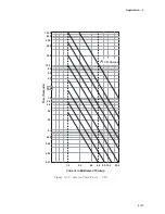
Figure 2-7
Third Harmonic Undervoltage (27TN) Protection Characteristics
27TN Third-Harmonic Undervoltage,
Neutral Circuit
For ground faults near the stator neutral, the third-
harmonic (180/150 Hz) neutral undervoltage function
(27TN) provides stator ground-fault protection for
high-impedance-grounded generator applications
(See Figure 2-7). When used in conjunction with
the fundamental neutral overvoltage (60/50Hz)
function (59N), 100% stator ground-fault protection
can be provided. This is illustrated in Figure 2-7.
The 27TN function supervision can be configured
by the user to be either independent positive-
sequence undervoltage element or forward power
flow element, or both. Supervision can prevent
tripping when the generator field is not energized
or the unit is not yet synchronized.
The 27TN setting depends on the actual third-
harmonic neutral voltage level seen during normal
operation of the generator. The setting should be
about 50% of the minimum third-harmonic voltage
observed during various loading conditions. This
can be most conveniently measured during
commissioning of the relay. Since the relay
measures the 3rd harmonic voltage levels and
will display those values directly, no additional
equipment is required. The undervoltage inhibit
setting should be about 80% to 90% of the nominal
voltage. The ranges and increments are presented
in Table 2-5.
N
O
I
T
C
N
U
F
E
G
N
A
R
T
N
I
O
P
T
E
S
T
N
E
M
E
R
C
N
I
)
N
T
7
2
(
t
i
u
c
r
i
C
l
a
r
t
u
e
N
,
e
g
a
t
l
o
v
r
e
d
n
U
c
i
n
o
m
r
a
H
-
d
r
i
h
T
2
#
,
1
#
p
u
k
c
i
P
V
0
.
0
2
o
t
3
.
0
V
1
.
0
2
#
,
1
#
y
a
l
e
D
e
m
i
T
s
e
l
c
y
C
0
6
1
8
o
t
1
e
l
c
y
C
1
t
i
b
i
h
n
I
e
g
a
t
l
o
v
r
e
d
n
U
2
#
,
1
#
)
e
c
n
e
u
q
e
s
e
v
i
t
i
s
o
p
(
V
0
8
1
o
t
5
V
1
t
i
b
i
h
n
I
r
e
w
o
p
r
e
d
n
U
2
#
,
1
#
u
p
0
0
0
.
3
o
t
2
0
0
.
0
u
p
1
0
0
.
0
Table 2-5
Third Harmonic Undervoltage, Neutral Circuit (27TN) Setpoint Ranges
Содержание M-3425
Страница 1: ...Instruction Book M 3425 Generator Protection ...
Страница 14: ... 13 M 3425 Generator Protection Relay Figure 1 External Connections ...
Страница 33: ...x M 3425 Instruction Book This Page Left Intentionally Blank ...
Страница 89: ...M 3425 Instruction Book 2 52 This Page Left Intentionally Blank ...
Страница 125: ...1 3 A B C M 3425 Instruction Book 4 26 This Page Left Intentionally Blank ...
Страница 187: ...M 3425 Instruction Book 6 50 This Page Left Intentionally Blank ...
Страница 207: ...M 3425 Instruction Book C 4 This Page Left Intentionally Blank ...
Страница 209: ...D 2 M 3425 Instruction Book Figure D 1 Volts Hz 24 Inverse Curve Family 1 Inverse Square ...
Страница 210: ...Inverse Time Curves Appendix D D 3 Figure D 2 Volts Hz 24 Inverse Family Curve 2 ...
Страница 211: ...D 4 M 3425 Instruction Book Figure D 3 Volts Hz 24IT Inverse Curve Family 3 ...
Страница 212: ...Inverse Time Curves Appendix D D 5 Figure D 4 Volts Hz 24IT Inverse Curve Family 4 ...
Страница 215: ...D 8 M 3425 Instruction Book Figure D 5 Definite Time Overcurrent Curve ...
Страница 216: ...Inverse Time Curves Appendix D D 9 Figure D 6 Inverse Time Overcurrent Curve ...
Страница 217: ...D 10 M 3425 Instruction Book Figure D 7 Very Inverse Time Overcurrent Curve ...
Страница 218: ...Inverse Time Curves Appendix D D 11 Figure D 8 Extremely Inverse Time Overcurrent Curve ...
Страница 223: ...D 16 M 3425 Instruction Book This Page Intentionally Left Blank ...


