


M-3425 Instruction Book
6–28
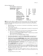
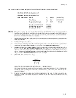
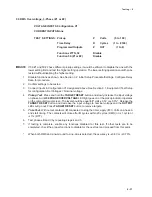
50 Instantaneous Phase Overcurrent
VOLTAGE INPUTS: Configuration V1
CURRENT INPUTS: Configuration C1
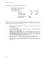
TEST SETTINGS:
Pickup
P
Amps
(1.0 to 240)
Programmed Outputs
Z
OUT
(1 to 8)
Functions 27TN, 32, 51T
Disable
Functions 51V, 87, 87GD
Disable
■
■
■
■
■
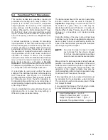
NOTE: Although no voltage input is required for the testing of the 50 function, it is suggested that Nominal
Volts be applied to restrain the functions which use both voltage and current inputs for operation.
If other functions operate during these tests they will need to also be disabled for the test and
enabled after the tests are complete.
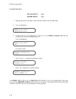
1.
Disable functions as shown. See Section 3.2, Initial Setup Procedure/Settings, Configure Relay
Data, for procedure.
2.
Confirm settings to be tested.
3.
Connect inputs in Configuration V1 and C1 designated above. See Section 6.1, Equipment/Test
Setup. Set the three-phase voltages V
A
, V
B
, and V
C
to the Nominal Voltage value.
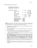
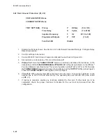
4.
Pickup Test: Hold the TARGET RESET button in and slowly increase current input 3 (C phase)
until the PHASE OVERCURRENT 50 LED light goes on or the pickup indicator operates on the
computer target screen. The current level of operation will be (P) amps ±0.1 amps or ±3%.
Release the TARGET RESET button and decrease the current and the OUTPUT LEDs will go out.
Press TARGET RESET button to remove targets.
5.
Time Test: With output contacts (Z) connected to stop the timer, apply approximately 110% of P
amps and start timing. The operating time will be O2 cycles. Reduce input 3 current to 0 amps.
6.
Test may be repeated using inputs 1 (A phase) and 2 (B phase) individually.
7.
If testing is complete, enable any functions disabled for this test. If other tests are to be
completed, check the proper functions to disable for the next test and proceed from this
configuration.
Содержание M-3425
Страница 1: ...Instruction Book M 3425 Generator Protection ...
Страница 14: ... 13 M 3425 Generator Protection Relay Figure 1 External Connections ...
Страница 33: ...x M 3425 Instruction Book This Page Left Intentionally Blank ...
Страница 89: ...M 3425 Instruction Book 2 52 This Page Left Intentionally Blank ...
Страница 125: ...1 3 A B C M 3425 Instruction Book 4 26 This Page Left Intentionally Blank ...
Страница 187: ...M 3425 Instruction Book 6 50 This Page Left Intentionally Blank ...
Страница 207: ...M 3425 Instruction Book C 4 This Page Left Intentionally Blank ...
Страница 209: ...D 2 M 3425 Instruction Book Figure D 1 Volts Hz 24 Inverse Curve Family 1 Inverse Square ...
Страница 210: ...Inverse Time Curves Appendix D D 3 Figure D 2 Volts Hz 24 Inverse Family Curve 2 ...
Страница 211: ...D 4 M 3425 Instruction Book Figure D 3 Volts Hz 24IT Inverse Curve Family 3 ...
Страница 212: ...Inverse Time Curves Appendix D D 5 Figure D 4 Volts Hz 24IT Inverse Curve Family 4 ...
Страница 215: ...D 8 M 3425 Instruction Book Figure D 5 Definite Time Overcurrent Curve ...
Страница 216: ...Inverse Time Curves Appendix D D 9 Figure D 6 Inverse Time Overcurrent Curve ...
Страница 217: ...D 10 M 3425 Instruction Book Figure D 7 Very Inverse Time Overcurrent Curve ...
Страница 218: ...Inverse Time Curves Appendix D D 11 Figure D 8 Extremely Inverse Time Overcurrent Curve ...
Страница 223: ...D 16 M 3425 Instruction Book This Page Intentionally Left Blank ...


