


1
3
A
B
C
4–3
Remote Operation – 4
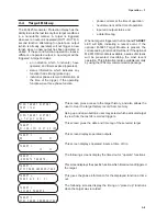
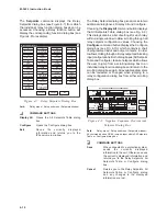
Individual relay communication addresses should
be between 1 and 200. The dead sync time, while
not critical for most communication networks, should
be programmed to match the communications
channels baud rate (see Table 4-1, below).
e
t
a
R
d
u
a
B
e
m
i
T
c
n
y
S
-
d
a
e
D
0
0
6
9
s
m
4
0
0
8
4
s
m
8
0
0
4
2
s
m
6
1
0
0
2
1
s
m
2
3
0
0
6
s
m
4
6
0
0
3
s
m
8
2
1
Table 4-1
Dead-Sync Time
Installing the Modems
Using IPScom to interrogate, set or monitor the
relay via a modem requires both a remote modem
connected at the relay location and a local modem
connected to the computer with IPScom installed.
In order to use IPScom to communicate with the
relay via a modem, the following must be provided
with the unit:
•
An external modem (300 baud or higher),
capable of understanding standard AT
commands.
•
Serial modem cable with 9-pin connector
for the unit and the applicable connector
for the modem.
■
NOTE: Any compatible modem may be used;
however, the unit only communicates at
300 to 9600 baud.
Similarly, the computer running IPScom must also
have access to an internal or external compatible
modem.
The local modem can be initialized, using IPScom,
by connecting the modem to the computer, and
selecting the COMM menu in IPScom. Select
MODEM, enter the required information, and finally
select INITIALIZE from the expanded
Communications dialog box. The following steps
outline the initialized modem setup procedure.
Setting Up the M-3425 Generator Protection
Relay for Communication
The initial setup of the relay for communication
must be completed by the optional M-3931 HMI
Module or via direct serial connection.
For units shipped without the optional HMI Module,
the communication parameters may be altered by
first establishing communication using the default
parameters and the IPSutil™ program.
IPSutil is an auxiliary program shipped on the same
disk with the IPScom
®
program. It is used
exclusively for altering communication and setup
parameters on units shipped without the M-3931
HMI Module.
The following communication parameters must be
set for proper operation:
COM1 Baud Rate: Standard baud rates from 300 to
9600 are available.
COM2 Baud Rate: Standard baud rates from 300 to
9600 are available. COM2 and COM3 share the
same baud rate (see Table 5.1, Jumpers).
COM2 Dead Sync Time: This delay establishes
the line idle time to re-sync packet communication.
Dead sync time should be programmed based on
the channel’s baud rate.
COM2 Protocol: BECO 2200 or MODBUS protocol
is supported on COM2.
COM2 Parity: None, odd or even parity is available
if MODBUS protocol is selected.
COM3 Dead Sync Time: This delay establishes
the line idle time to re-sync packet communication.
Dead sync time should be programmed based on
the channel’s baud rate.
COM3 Protocol: BECO 2200 or MODBUS protocol
is supported on COM3.
COM3 Parity: None, odd or even parity is available
if MODBUS protocol is selected.
Communications Address: For multidrop networks,
each device must have a unique address.
Communication Access Code: If additional link
security is desired, a communication access code
can be programmed. Like the user access codes, if
the communication access code is set to 9999
(default), communication security is disabled.
Содержание M-3425
Страница 1: ...Instruction Book M 3425 Generator Protection ...
Страница 14: ... 13 M 3425 Generator Protection Relay Figure 1 External Connections ...
Страница 33: ...x M 3425 Instruction Book This Page Left Intentionally Blank ...
Страница 89: ...M 3425 Instruction Book 2 52 This Page Left Intentionally Blank ...
Страница 125: ...1 3 A B C M 3425 Instruction Book 4 26 This Page Left Intentionally Blank ...
Страница 187: ...M 3425 Instruction Book 6 50 This Page Left Intentionally Blank ...
Страница 207: ...M 3425 Instruction Book C 4 This Page Left Intentionally Blank ...
Страница 209: ...D 2 M 3425 Instruction Book Figure D 1 Volts Hz 24 Inverse Curve Family 1 Inverse Square ...
Страница 210: ...Inverse Time Curves Appendix D D 3 Figure D 2 Volts Hz 24 Inverse Family Curve 2 ...
Страница 211: ...D 4 M 3425 Instruction Book Figure D 3 Volts Hz 24IT Inverse Curve Family 3 ...
Страница 212: ...Inverse Time Curves Appendix D D 5 Figure D 4 Volts Hz 24IT Inverse Curve Family 4 ...
Страница 215: ...D 8 M 3425 Instruction Book Figure D 5 Definite Time Overcurrent Curve ...
Страница 216: ...Inverse Time Curves Appendix D D 9 Figure D 6 Inverse Time Overcurrent Curve ...
Страница 217: ...D 10 M 3425 Instruction Book Figure D 7 Very Inverse Time Overcurrent Curve ...
Страница 218: ...Inverse Time Curves Appendix D D 11 Figure D 8 Extremely Inverse Time Overcurrent Curve ...
Страница 223: ...D 16 M 3425 Instruction Book This Page Intentionally Left Blank ...


