


M-3425 Instruction Book
2–32
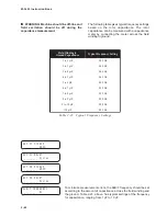
51V Inverse Time Phase Overcurrent with
Voltage Control/Restraint
Time-overcurrent relays, one per phase, are used to
trip circuits selectively and to time-coordinate with
other up- or downstream relays. For this function,
eight complete series of inverse time tripping
characteristics are included. The same descriptions
and nomenclature which are traditionally used with
electromechanical relays are used in the relay.
Thus, the curve families to be chosen are definite
time, inverse, very inverse, extremely inverse and
four IEC curves. In the menu, these are abbreviated
as DEF, INV, VINV, EINV, IECI, IECVI, IECEI, and
IECLT. Within each family, the operator selects
time dial setting and pickup (tap) setting, just as
with electromechanical relays. Ranges and
increments are presented in Table 2-14.
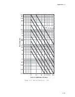
The curves available for use are shown in Appendix
D, Inverse Time Curves. They cover a range from
1.5 to 20 times the pickup setting. An additional one
cycle time delay should be added to these curves in
order to obtain the relay operating time. Inverse
time curves saturate beyond 20 times pickup. For
currents in excess of 20 times pickup, operating
times are fixed at the 20 time pickup level. The
particular settings will be made by information from
short-circuit fault studies and knowledge of the
coordination requirements with other devices in the
system that respond to time overcurrent.
51V is a true three-phase function, in that the relay
incorporates separate integrating timers on each
phase.
The inverse time overcurrent function can be voltage
controlled (VC), voltage restrained (VR), or neither.
For voltage-controlled operation, the function is not
active unless the voltage is below the voltage control
setpoint. This philosophy is used to confirm that the
overcurrent is due to system fault. When applied,
most users will set voltage control limits in the
range of 0.7 to 0.01 per unit RMS voltage. When
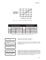
voltage restraint is selected (See Figure 2-15,
Voltage Restraint (51VR) Characteristic), the pickup
setting is continuously modified in proportion to the
collapsing terminal voltage. The voltage restraint
function is well-suited to small generators with
relatively short time constants.
The 51V function should be blocked by fuse loss if
in the voltage control mode. Fuse loss blocking is
not desirable for voltage restraint mode because the
pickup is automatically held at 100% pickup during
fuse loss conditions, and operation will continue as
normal.
The internally derived voltage used to realize the
voltage control or restraint feature depends on the
configured VT configuration and the Delta-Y
Transform setting (see Section 2.1, Configuration,
Relay System Setup). Table 2-15, Delta/Wye
Transformer Voltage-Current Pairs describes the
calculation for the various system VT configurations.
N
O
I
T
C
N
U
F
E
G
N
A
R
T
N
I
O
P
T
E
S
T
N
E
M
E
R
C
N
I
)
V
1
5
(
t
n
i
a
r
t
s
e
R
e
g
a
t
l
o
V
r
o
l
o
r
t
n
o
C
e
g
a
t
l
o
V
h
t
i
w
,
t
n
e
r
r
u
c
r
e
v
O
e
m
i
T
e
s
r
e
v
n
I
p
u
k
c
i
P
A
0
0
.
2
1
o
t
0
5
.
0
)
A
0
4
.
2
o
t
0
1
.
0
(
A
1
0
.
0
e
v
r
u
C
c
i
t
s
i
r
e
t
c
a
r
a
h
C
e
s
r
e
v
n
I
y
r
e
V
/
e
s
r
e
v
n
I
/
e
m
i
T
e
t
i
n
i
f
e
D
s
e
v
r
u
C
C
E
I
/
e
s
r
e
v
n
I
y
l
e
m
e
r
t
x
E
/
l
a
i
D
e
m
i
T
0
.
1
1
o
t
5
.
0
)
s
e
v
r
u
C
C
E
I
(
0
1
.
1
o
t
5
0
.
0
1
.
0
1
0
.
0
)
C
V
(
l
o
r
t
n
o
C
e
g
a
t
l
o
V
V
0
8
1
o
t
5
V
1
r
o
)
R
V
(
t
n
i
a
r
t
s
e
R
e
g
a
t
l
o
V
t
n
i
a
r
t
s
e
R
r
a
e
n
i
L
—
Table 2-14
Inverse Time Overcurrent with Voltage Control/Voltage Restraint (51VC/VR)
Setpoint Ranges
Содержание M-3425
Страница 1: ...Instruction Book M 3425 Generator Protection ...
Страница 14: ... 13 M 3425 Generator Protection Relay Figure 1 External Connections ...
Страница 33: ...x M 3425 Instruction Book This Page Left Intentionally Blank ...
Страница 89: ...M 3425 Instruction Book 2 52 This Page Left Intentionally Blank ...
Страница 125: ...1 3 A B C M 3425 Instruction Book 4 26 This Page Left Intentionally Blank ...
Страница 187: ...M 3425 Instruction Book 6 50 This Page Left Intentionally Blank ...
Страница 207: ...M 3425 Instruction Book C 4 This Page Left Intentionally Blank ...
Страница 209: ...D 2 M 3425 Instruction Book Figure D 1 Volts Hz 24 Inverse Curve Family 1 Inverse Square ...
Страница 210: ...Inverse Time Curves Appendix D D 3 Figure D 2 Volts Hz 24 Inverse Family Curve 2 ...
Страница 211: ...D 4 M 3425 Instruction Book Figure D 3 Volts Hz 24IT Inverse Curve Family 3 ...
Страница 212: ...Inverse Time Curves Appendix D D 5 Figure D 4 Volts Hz 24IT Inverse Curve Family 4 ...
Страница 215: ...D 8 M 3425 Instruction Book Figure D 5 Definite Time Overcurrent Curve ...
Страница 216: ...Inverse Time Curves Appendix D D 9 Figure D 6 Inverse Time Overcurrent Curve ...
Страница 217: ...D 10 M 3425 Instruction Book Figure D 7 Very Inverse Time Overcurrent Curve ...
Страница 218: ...Inverse Time Curves Appendix D D 11 Figure D 8 Extremely Inverse Time Overcurrent Curve ...
Страница 223: ...D 16 M 3425 Instruction Book This Page Intentionally Left Blank ...


