


6–7
Testing – 6
3.
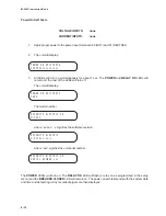
Press ENTER. The following is displayed:
INPUT NUMBER 1
CIRCUIT OPEN
4.
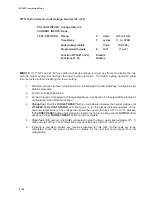
Connect IN COM terminal (terminal #11)
to IN1 terminal (terminal #10). See Table
6-3.
Alternatively, if this specific input is being
used in this application and the external
wiring is complete, the actual external
status input contact can be manually
closed. This will test the input contact
operation
and the external wiring to the
input contacts. The following is
immediately displayed:
INPUT NUMBER 1
CIRCUIT CLOSED
5.
Disconnect IN COM terminal (terminal
#11) from IN1 terminal (terminal #10).
The following is immediately displayed:
INPUT NUMBER 1
CIRCUIT OPEN
6.
Press ENTER. The following is displayed:
INPUT NUMBER
1
7.
Use the up arrow button to go to the next
input. Repeat the procedure using the
contacts as shown in Table 6-3. When
finished, press EXIT to return to the
DIAGNOSTIC MODE menu.
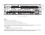
Choose outputs 2 through 8 by using the up arrow
and down arrow buttons to turn all relays or outputs
to the energized or ON position. Note that when
each output is turned on, the appropriate red
OUTPUT LED turns on and stays on.
The DMM can now be used to verify the position of
the output contacts in the operated or ON position.
The readings should be the opposite of the initial
reading above. All outputs should be returned to
their initial de-energized or OFF positions (OUTPUT
LEDs will go out when each output is turned off)
before pushing EXIT to return to the DIAGNOSTIC
MODE menu.
Input Test (Status)
The INPUT TEST menu enables the user to
determine the status of the individual status inputs.
Individual inputs can be selected by number using
the up and down arrow buttons. The status of the
input will then be displayed.
T
U
P
N
I
R
E
B
M
U
N
N
O
M
M
O
C
L
A
N
I
M
R
E
T
L
A
N
I
M
R
E
T
)
b
2
5
(
1
1
1
0
1
2
1
1
9
3
1
1
8
4
1
1
7
5
1
1
6
6
1
1
5
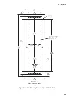
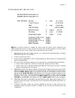
Table 6-3
Input Contacts
1.
When OUTPUT TEST (RELAY) is
displayed, press the right arrow button
until the following is displayed:
INPUT TEST (STATUS)
output INPUT led target
!
2.
Press ENTER. The following is displayed:
INPUT NUMBER
1
Содержание M-3425
Страница 1: ...Instruction Book M 3425 Generator Protection ...
Страница 14: ... 13 M 3425 Generator Protection Relay Figure 1 External Connections ...
Страница 33: ...x M 3425 Instruction Book This Page Left Intentionally Blank ...
Страница 89: ...M 3425 Instruction Book 2 52 This Page Left Intentionally Blank ...
Страница 125: ...1 3 A B C M 3425 Instruction Book 4 26 This Page Left Intentionally Blank ...
Страница 187: ...M 3425 Instruction Book 6 50 This Page Left Intentionally Blank ...
Страница 207: ...M 3425 Instruction Book C 4 This Page Left Intentionally Blank ...
Страница 209: ...D 2 M 3425 Instruction Book Figure D 1 Volts Hz 24 Inverse Curve Family 1 Inverse Square ...
Страница 210: ...Inverse Time Curves Appendix D D 3 Figure D 2 Volts Hz 24 Inverse Family Curve 2 ...
Страница 211: ...D 4 M 3425 Instruction Book Figure D 3 Volts Hz 24IT Inverse Curve Family 3 ...
Страница 212: ...Inverse Time Curves Appendix D D 5 Figure D 4 Volts Hz 24IT Inverse Curve Family 4 ...
Страница 215: ...D 8 M 3425 Instruction Book Figure D 5 Definite Time Overcurrent Curve ...
Страница 216: ...Inverse Time Curves Appendix D D 9 Figure D 6 Inverse Time Overcurrent Curve ...
Страница 217: ...D 10 M 3425 Instruction Book Figure D 7 Very Inverse Time Overcurrent Curve ...
Страница 218: ...Inverse Time Curves Appendix D D 11 Figure D 8 Extremely Inverse Time Overcurrent Curve ...
Страница 223: ...D 16 M 3425 Instruction Book This Page Intentionally Left Blank ...


