


Operation
EL6910
25
Version: 1.8.0
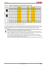
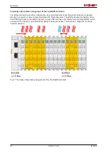
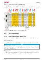
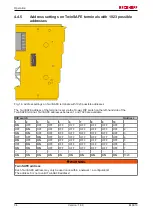
Thermally favorable arrangement of the TwinSAFE terminals
The following structure is thermally favorable, since between the coupler / power supply terminal and
terminals with rather high waste heat, terminals with low current consumption and thus rather low waste heat
are placed.
Fig. 8: Thermally favorable arrangement of the TwinSAFE terminals
4.2.4
Electrical installation
4.2.4.1
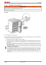
Connections within a Bus Terminal block
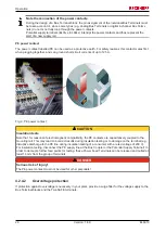
The electric connections between the Bus Coupler and the Bus Terminals are automatically realized by
joining the components:
Spring contacts (E-bus)
The six spring contacts of the E-bus deal with the transfer of the data and the supply of the Bus Terminal
electronics.
NOTE
Observe the E-bus current
Observe the maximum current that your Bus Coupler can supply to the E-bus! Use the EL9410 Power Sup-
ply Terminal if the current consumption of your terminals exceeds the maximum current that your Bus Cou-
pler can feed to the E-bus supply.
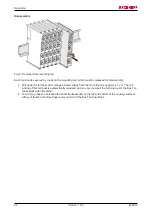
Power contacts
The power contacts deal with the supply for the field electronics and thus represent a supply rail within the
Bus Terminal block. The power contacts are supplied via terminals on the Bus Coupler.
Содержание TwinSAFE EL6910
Страница 1: ...Operation Manual for EL6910 TwinSAFE Logic Terminal 1 8 0 2019 01 09 Version Date...
Страница 2: ......
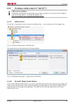
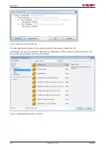
Страница 62: ...Operation EL6910 62 Version 1 8 0 Fig 63 Check Safe Addresses context menu Fig 64 Check Safe Addresses dialog...
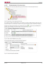
Страница 69: ...Operation EL6910 69 Version 1 8 0 Fig 73 The Safety Project Online View tab...
Страница 71: ...Operation EL6910 71 Version 1 8 0 Fig 75 Group Status Online ERROR Fig 76 Group Status Online STOP...
Страница 136: ...Appendix EL6910 136 Version 1 8 0 5 2 Certificates...
Страница 137: ...Appendix EL6910 137 Version 1 8 0...