


Commissioning/configuration of IO-Link master/device
EPI3xxx, ERI3xxx
82
Version: 1.2
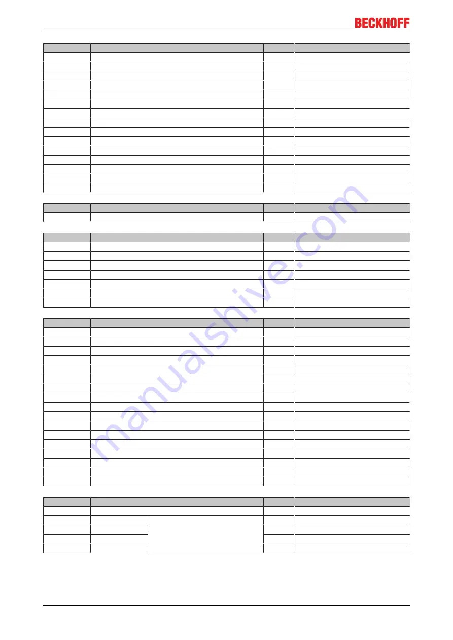
Subindex
Name
Flags
Default value
0x0830:0
AI Settings Ch 4
RW
18
0x0830:01
Enable User Scale
RW
0x00 (0
dec
)
0x0830:02
Presentation
RW
Signed
0x0830:05
Siemens bits
RW
0x00 (0
dec
)
0x0830:07
Enable Limit 1
RW
0x00 (0
dec
)
0x0830:08
Enable Limit 2
RW
0x00 (0
dec
)
0x0830:0A
Enable User Calibration
RW
0x00 (0
dec
)
0x0830:0B
Enable Vendor Calibration
RW
0x01 (1
dec
)
0x0830:0E
Swap Limit Bits
RW
0x00 (0
dec
)
0x0830:11
User Scale Offset
RW
0x0000 (0
dec
)
0x0830:12
User Scale Gain
RW
0x00010000 (65536
dec
)
0x0830:13
Limit 1
RW
0x0000 (0
dec
)
0x0830:14
Limit 2
RW
0x0000 (0
dec
)
0x0830:17
User Calibration Offset
RW
0x0000 (0
dec
)
0x0830:18
User Calibration Gain
RW
0x4000 (16384
dec
)
Subindex
Name
Flags
Default value
0x083E:01
ADC raw value
RO
0x0000 (0
dec
)
Subindex
Name
Flags
Default value
0x083F:0
AI Vendor Data Ch 4
RO
12
0x083F:01
R0 Offset
RO
0x0000 (0
dec
)
0x083F:02
R0 Gain
RO
0x4000 (16384
dec
)
0x083F:03
R1 Offset
RO
0x0000 (0
dec
)
0x083F:04
R1 Gain
RO
0x4000 (16384
dec
)
0x083F:05
R2 Offset
RO
0x0000 (0
dec
)
0x083F:06
R2 Gain
RO
0x4000 (16384
dec
)
Subindex
Name
Flags
Default value
0x0A00:0
Diagnostics
RO
2
0x0A00:01
Overtemperature
RO
0
0x0A00:02
Short detected
RO
0
0x0A00:03
L
+
low
RO
0
0x0A00:04
2L
+
low
RO
0
0x0A00:05
2L
+
stat
RO
0
0x0A00:06
Reserved
RO
0
0x0A00:07
Reserved
RO
0
0x0A00:08
Reserved
RO
0
0x0A00:09
Reserved
RO
0
0x0A00:0A
Reserved
RO
0
0x0A00:0B
Reserved
RO
0
0x0A00:0C
Reserved
RO
0
0x0A00:0D
Reserved
RO
0
0x0A00:0E
Reserved
RO
0
0x0A00:0E
Reserved
RO
0
0x0A00:10
Reserved
RO
0
Subindex
Name
Flags
Default value
0x3800:0
AI Range Settings
RW
10
0x3800:01
Input type Ch1
0
dec
: -10 V…+10 V
1
dec
: 0 mA…20 mA
2
dec
: 4 mA…20 mA
6
dec
: 0 V…+10 V
RW
0x0000 (0
dec
)
0x3800:02
Input type Ch2
RW
0x0000 (0
dec
)
0x3800:03
Input type Ch3
RW
0x0000 (0
dec
)
0x3800:04
Input type Ch4
RW
0x0000 (0
dec
)
Key
Flags:
Содержание EPI3 Series
Страница 1: ...Documentation EPI3xxx ERI3xxx IO Link Box Modules with analog inputs 1 2 2018 07 10 Version Date ...
Страница 2: ......
Страница 12: ...IO Link basics EPI3xxx ERI3xxx 12 Version 1 2 Fig 3 IO Link overview Peer to peer communication ...
Страница 31: ...Commissioning configuration of IO Link master device EPI3xxx ERI3xxx 31 Version 1 2 Fig 28 IO Link tab ...


