IPC@CHIP SC2x3
Hardware Manual V1.02 [01.03.09]
©2000-2009 BECK IPC GmbH
Page 11
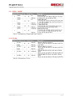
4.3 Local Plus Bus
Pin Name
Pin
Con
Type
Description
LP_CS0#
116
X1
OUT[8mA]
Reserved. Do not connect.
(internal 100kOhm pullup)
LP_CS1#
113
X1
OUT[8mA]
Local Plus Bus Chip Select
(internal 100kOhm pullup)
LP_CS2#
112
X1
OUT[8mA]
Reserved. Do not connect.
(internal 100kOhm pullup)
LP_CS3#
111
X1
OUT[8mA]
Local Plus Bus Chip Select
(internal 100kOhm pullup)
LP_CS4#
110
X1
OUT[8mA]
ATA Chip Select CS0#
(internal 100kOhm pullup)
LP_CS5#
108
X1
OUT[8mA]
ATA Chip Select CS1#
(internal 100kOhm pullup)
LP_RW
91
X1
OUT[8mA]
Read/Write control signal, 1 = Read, 0 = Write
LP_ALE#
93
X1
OUT[8mA]
Local Plus Bus Address Latch Enable
LP_TS#
94
X1
OUT[8mA]
Local Plus Bus Transfer Start
LP_ACK#
95
X1
IN/
OUT[8mA]
Local Plus Bus External Acknowledge input
(Open
Drain with internal pullup)
LP_OE#
96
X1
OUT[8mA]
Local Plus Bus Output Enable
Table 4-1: Pin Description of Local Plus Bus control signals
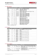
4.4 ATA Interface
Pin Name
Pin
Con
Type
Description
ATA_IOR#
100
X1
OUT[8mA]
ATA I/O Read output
(Active Low)
This pin indicates a read transaction on ATA Interface
ATA_IOW#
101
X1
OUT[8mA]
ATA I/O Write output
(Active Low)
This pin indicates a write transaction on ATA Interface
ATA_ISOLATION
99
X1
OUT[8mA]
ATA Isolation
(Active High)
This pin is an active high signal to control external ATA
transceiver devices and to isolate the ATA bus from the
shared Local Plus bus.
ATA_INTRQ
102
X1
IN
ATA Interrupt
(Active High with internal 10kOhm
pulldown)
This pin is the external ATA interrupt request.
ATA_DACK#
104
X1
IN
ATA DMA Acknowledge
(Active Low)
ATA_IOCHRDY
103
X1
IN
ATA I/O Channel Ready
(Active High with internal
10kOhm pullup)
This pin is used to extend ATA bus accesses
ATA_DRQ
105
X1
IN
ATA DMA Request
(Active High with internal 10kOhm
pulldown)
Table 4-2: Pin Description of ATA control signals


