IPC@CHIP SC2x3
Hardware Manual V1.02 [01.03.09]
©2000-2009 BECK IPC GmbH
Page 15
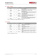
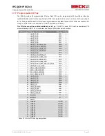
4.8 PSC3
– UART3/SPI
#PSC3 Pin Name
Pin
Con
Type
Description
0
TXD3
53
X3
OUT[4mA]
Transmit Data 3 Out
This pin provides serial Transmit data to
the system from serial port 3.
USB2_OE
OUT[4mA]
USB 2 Output Enable
(Active Low)
This pin is used to enable the transceiver to
transmit data on the bus.
PIO10
I/O[4mA]
This pin can also be used as PIO10.
TXD3
76
X3
OUT[RS232]
Transmit Data 1 Out
This pin provides the signal TXD3 using
RS232 level.
1
RXD3
51
X3
IN
Receive Data 3 In
This pin provides serial Receive Data from
the system to serial port 3.
USB2_TXN
OUT[4mA]
USB 2 Transmit Negative
This pin is the negative output to the
differential driver.
PIO11
I/O[4mA]
This pin can also be used as PIO11.
RXD3
75
X3
IN[RS232]
Receive Data 1 In
This pin provides the signal RXD1 using
RS232 level.
2
RTS3
52
X3
OUT[4mA]
Ready to send 3 Out
This pin provides the Ready to Send output
for serial port 3. It provides the
handshaking output for serial port 3.
USB2_TXP
OUT[4mA]
USB 2 Transmit Positive
This pin is the positive output to the
differential driver.
PIO12
I/O[4mA]
This pin can also be used as PIO12.
3
CTS3
47
X3
IN
Clear to Send 3 In
This pin provides the Clear to Send input
for serial port 3. It provides the
handshaking input for serial port 3.
USB2_RXD
IN
USB 1 Receive Data
This pin is the data input from the
differential driver.
PIO13
I/O[4mA]
This pin can also be used as PIO13.
4
DCD3
48
X3
IN
Data Carrier Detect 3 Input
In the enhanced UART mode this signal
must be assert during the data
transmission.
USB2_RXP
IN
USB 2 Receive Positive
This pin is used to detect single ended
zero, error conditions, and interconnected
speed.
LP_CS6#
OUT[8mA]
Local Plus Bus Chip Select shared with
PSC3
PIO14
I/O[8mA]
This pin can also be used as PIO14.


