IPC@CHIP SC2x3
Hardware Manual V1.02 [01.03.09]
©2000-2009 BECK IPC GmbH
Page 13
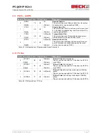
#USB1 Pin Name
Pin
Con
Type
Description
8
USB1_SUSPEND
PIO27
30
X3
OUT[4mA]
I/O[4mA]
USB 1 Suspend
(Active High)
This pin enables a low-power state while the
USB bus is inactive or can be used as PIO27.
CTS5
IN
Clear to Send 5 In
This pin provides the Clear to Send input for
serial port 5. It provides the handshaking input
for serial port 5.
9
USB1_OVRCNT
PIO28
29
X3
IN
I/O[4mA]
USB 1 Overcurrent Detection
This pin can also be used as PIO28.
Table 4-3: Pin Description of USB1 - UART4+5 Interface
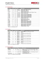
4.6 PSC1
– UART1
#PSC1 Pin Name
Pin
Con
Type
Description
0
TXD1
PIO0
65
X3
OUT[4mA]
I/O[4mA]
Transmit Data 1 Out
This pin provides serial Transmit data to the system
from serial port 1 or can be used as PIO0
TXD1
72
X3
OUT[RS232]
Transmit Data 1 Out
This pin provides the signal TXD1 using RS232 level.
1
RXD1
PIO1
63
X3
IN
I/O[4mA]
Receive Data 1 In
This pin provides serial Receive Data from the system
to serial port 1 or can be used as PIO1
RXD1
71
X3
IN[RS232]
Receive Data 1 In
This pin provides the signal RXD1 using RS232 level.
2
RTS1
PIO2
64
X3
OUT[4mA]
I/O[4mA]
Ready to Send 1 Out
This pin provides the Ready to Send output for serial
port 1. It provides the handshaking output for serial
port 1 or can be used as PIO2.
3
CTS1
PIO3
59
X3
IN
I/O[4mA]
Clear to Send 1 In
This pin provides the Clear to Send input for serial
port 1. It provides the handshaking input for serial port
1 or can be used as PIO3.
4
DCD1
PIO4
62
X3
IN
I/O[4mA]
Data Carrier Detect 1 Input
In the enhanced UART mode this signal must be
assert during the data transmission.
This pin can slo be used as PIO4.
Table 4-4: Pin Description of Programmable Serial Controller 1


