IPC@CHIP SC2x3
Hardware Manual V1.02 [01.03.09]
©2000-2009 BECK IPC GmbH
Page 16
5
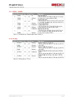
USB2_RXN
45
X3
IN
USB 2 Receive Negative
This pin is used to detect single ended zero
error conditions, and interconnected speed.
LP_CS7#
OUT[8mA]
Local Plus Bus Chip Select shared with
PSC3
PIO15
I/O[8mA]
This pin can also be used as PIO15.
6
MOSI
46
X3
OUT[4mA]
SPI Master Data Out/Slave Data In
USB2_PRTPWR
OUT[4mA]
USB 2 Port Power
(Active Low)
This pin can be used to enable the USB
port power output.
PIO16
I/O[4mA]
This pin can also be used as PIO16.
7
MISO
43
X3
IN
SPI Master Data In/Slave Data Out
USB2_SPEED
OUT[4mA]
USB 2 Speed
(Active High)
This pin controls the Edge Rate Control.
1=full speed, 0=low speed.
PIO17
I/O[4mA]
This pin can also be used as PIO17.
8
SS
44
X3
OUT[4mA]
SPI Slave Select
USB2_SUSPEND
OUT[4mA]
USB 2 Suspend
(Active High)
This pin enables a low-power state while
the USB bus is inactive.
PIO18
I/O[4mA]
This pin can also be used as PIO18.
9
SCK
41
X3
OUT[4mA]
SPI Serial Clock
USB2_OVRCNT
IN
USB 2 Overcurrent Detection
PIO19
I/O[4mA]
This pin can also be used as PIO19.
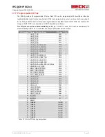
Table 4-6: Pin Description of Programmable Serial Controller 3


