


9
80-0042-00, Rev. 06.9
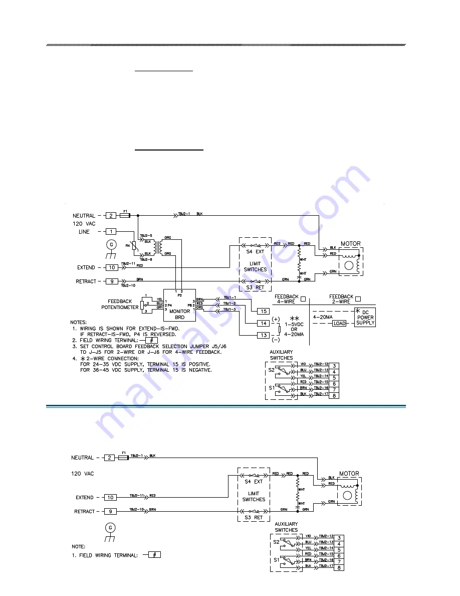
Option 5, Modulating
Direct AC Control with
Loop Powered
Position Feedback Signal
Customer must supply three wires to directly control the actuator motor direction: One 120 V ac line
to run Extend (terminal 10), one 120 V ac line to run Retract (terminal 9), and one neutral (terminal 2).
Customer may supply two additional wires to monitor a loop powered position feedback signal. The loop
powered position feedback signal must be connected to a “2-wire” type analog input that provides a dc
voltage over the signal wires (a dc voltage power supply must be wired in series with the signal wiring). If
the dc supply is 24 to 35 volts, connect to terminal 14 (-) and to terminal 15 (+). If the dc supply is 36 to 45
volts, reverse polarity and connect to terminal 14 (+) and to terminal 15 (-).
Direct AC Control with Actuator Powered Position Feedback Signal
Customer must supply three wires to directly control the actuator motor direction: One 120 V ac line
to run Extend (terminal 10), one 120 V ac line to run Retract (terminal 9), and one neutral (terminal 2).
Customer may supply two additional wires to monitor the analog position feedback signal: Connect to
terminal 13 (-) and to terminal 14 (+). If position feedback monitoring is desired, a 120 V ac line must
be connected to terminal 1. The drive’s feedback circuit power supply is derived from this 120 V ac line,
therefore the feedback signal must be wired to a “4-wire” type, non-powered analog input.
Option 3, Open/Close
Direct AC Control
Customer must supply three wires to directly control the actuator motor direction: one 120 V ac line to run
Extend (terminal 10), one 120 V ac line to run Retract (terminal 9) and one neutral (terminal 2).
Typical Wiring Diagram (Option 5)
Typical Wiring Diagram (Option 3)


