
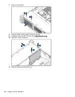


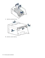


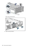


6.
Remove all riser cages.
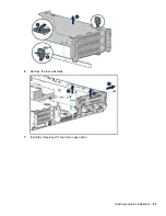
7.
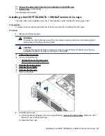
Connect the power cable to the drive backplane power connector on the system board.
8.
If connecting the data cable to the system board or a controller, connect the data cable.
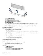
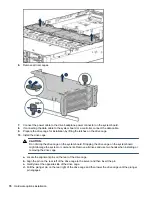
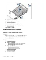
9.
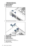
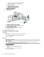
Prepare the drive cage for installation by lifting the latches on the drive cage.
10.
Install the drive cage:
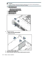
CAUTION:
Do not drop the drive cage on the system board. Dropping the drive cage on the system board
might damage the system or components. Remove all drives and use two hands when installing or
removing the drive cage.
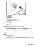
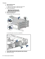
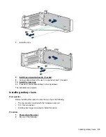
a.
Locate the alignment pins on the rear of the drive cage.
b.
Align the pin on the rear left of the drive cage to the server and then insert the pin.
c.
Gently lower the opposite side of the drive cage.
d.
Pull the plunger pin on the rear right of the drive cage and then lower the drive cage until the plunger
pin engages.
76
Hardware options installation
Содержание BCD221
Страница 7: ...Documentation feedback 157 Contents 7 ...
Страница 27: ...Component identification 27 ...
Страница 43: ...Operations 43 ...
Страница 74: ...9 Install the optical disk drive tray 10 Install the universal media bay 74 Hardware options installation ...
Страница 80: ...Remove the secondary wall blank 6 Remove the tertiary wall blank 80 Hardware options installation ...
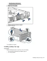
Страница 81: ...7 Install the drive cage compatible rear wall 8 Install the drive cage Hardware options installation 81 ...
Страница 123: ...LFF models Cable routing Front 8SFF drive options Box 1 to SAS Expander Cable routing Front 8SFF drive options 123 ...
Страница 124: ...Box 2 to SAS Expander All boxes 124 Cabling ...
Страница 126: ...Box 2 Box 3 126 Cabling ...
Страница 127: ...Cable routing Front 2SFF NVMe drive option for SFF Cable routing Front 2SFF NVMe drive option for SFF 127 ...