
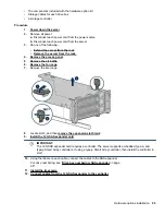


Procedure
1.
2.
Remove all power:
a.
Disconnect each power cord from the power source.
b.
Disconnect each power cord from the server.
3.
Do one of the following:
•
Extend the server from the rack
•
Remove the server from the rack
.
4.
.
5.
Do one of the following:
•
.
• If installed on LFF models, remove the midplane drive cage.
6.
7.
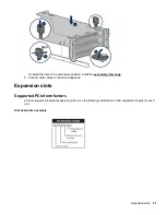
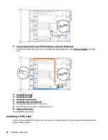
Disconnect the cable from the front power/USB 3.0 connector.
8.
Remove the power switch module. Retain the T-10 screw for later use.
9.
Route the cable through the opening in the front of the server, and then install the SID power switch
module. Secure the module using the existing screw.
CAUTION:
When routing cables, always be sure that the cables are not in a position where they can be
pinched or crimped.
Hardware options installation
105
Содержание BCD221
Страница 7: ...Documentation feedback 157 Contents 7 ...
Страница 27: ...Component identification 27 ...
Страница 43: ...Operations 43 ...
Страница 74: ...9 Install the optical disk drive tray 10 Install the universal media bay 74 Hardware options installation ...
Страница 80: ...Remove the secondary wall blank 6 Remove the tertiary wall blank 80 Hardware options installation ...
Страница 81: ...7 Install the drive cage compatible rear wall 8 Install the drive cage Hardware options installation 81 ...
Страница 123: ...LFF models Cable routing Front 8SFF drive options Box 1 to SAS Expander Cable routing Front 8SFF drive options 123 ...
Страница 124: ...Box 2 to SAS Expander All boxes 124 Cabling ...
Страница 126: ...Box 2 Box 3 126 Cabling ...
Страница 127: ...Cable routing Front 2SFF NVMe drive option for SFF Cable routing Front 2SFF NVMe drive option for SFF 127 ...