Installation
Operation manual
b maXX
BM4100 (NWR)
Document no.: 5.04052.09
71
7
7.18 Connection diagrams
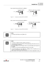
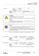
The figures from
to
show the connections for protective conduc-
tor, mains, chopper resistor, DC link.
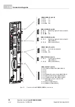
on page 74 shows the connection of
control voltage and the connections of the controller unit.
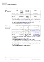
the connections of the function modules in the slots A to D.
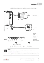
The electrical connections for the device
BM4135
are shown in the following figure:
at the back (back panel)
at the back (back panel)
Figure 29:
Electrical connections for mains, DC-link, upon others for BM4135
1D1, 1C1
DC-link
Ba+, Ba-
Chopper resistor
for discharge
in front (cover)
1U1, 1V1, 1W1
Mains connec-
tions
NOTE
X11-1 (ZKM) and X11-2 (RCD) must be short-circuited with a cable adapted for the mains
voltage.
Содержание b maXX 4100 Series
Страница 21: ...Safety Operation manual b maXX BM4100 NWR Document no 5 04052 09 21 of 142 2 Figure 2 Signs and labels BM416X ...
Страница 126: ...Baumüller accessories Operation manual b maXX BM4100 NWR Document no 5 04052 09 Baumüller Nürnberg GmbH 126 of 142 11 7 ...
Страница 138: ...Operation manual b maXX BM4100 NWR Document no 5 04052 09 Baumüller Nürnberg GmbH 138 of 142 Table of figures ...
Страница 142: ...Operation manual b maXX BM4100 NWR Document no 5 04052 09 Baumüller Nürnberg GmbH 142 of 142 Notes ...
Страница 143: ......


