background image

56-2 


9424200996 

Commissioning Testing 


BE1-11

m


front-panel display. Return the output to its original state, verifying that the output returns to its 

original state. Use the Metering Explorer in BESTCOMS

Plus

 to open the Reports, Sequence of 

Events screen. Click on the Download button and review the events associated with the output 

contact change. 

Step 3:    Repeat Step 2 to verify that operation of the alarm output relay (OUTA) initiates the appropriate 

alarm response. 

Virtual Selector Switches 

Purpose:

 To verify operation, labels, and logic settings of the 43 switches. 

Chapter Reference: 

Virtual Control Switches (43) 

Step 1:    Use the Settings Explorer in BESTCOMS

Plus

 to open the Control, Virtual Control Switches 

screen and verify the 43-1 through 43-5 mode, name label, on label, and off label. 

Step 2:    Use the Metering Explorer in BESTCOMS

Plus

 to open the Control, Virtual Switches screen and 

obtain the position of the five virtual selector switches. Alternately, the virtual selector switch 

positions can be obtained on the Metering > Control > Virtual Switches screen of the front-panel 

display. 

Step 3:    Obtain write access to the BE1-11

m

. For each virtual selector switch enabled in your logic 

scheme, change the switch position by following the procedure described in the 

Virtual Control 

Switches (43) 

chapter

.


Step 4:    Verify each switch position change on the Control, Virtual Switches screen of BESTCOMS

Plus


or on the front-panel display. 

Step 5:    Return each virtual selector switch to the original position. 
Step 6:    Use the Metering Explorer in BESTCOMS

Plus

 to open the Reports, Sequence of Events 

screen. Click on the Download button and review the events associated with the virtual switch 

activities. 

Virtual Control Switch 

Purpose:

 To verify operation and logic setting for the 101 switch. 

Chapter Reference:

 Breaker Control Switch (101) 

Step 1:    Use the Settings Explorer in BESTCOMS

Plus

 to open the Control, Breaker Control Switch 

screen and verify the 101 element mode. 

Step 2:    Use the Metering Explorer in BESTCOMS

Plus

 to open the Control, Breaker Control Switch 

screen and obtain the position of the breaker control switch. Alternately, the breaker control 

switch position can be obtained on the Metering > Control > 101 Breaker Control SW screen of 

the front-panel display. 

Step 3:    Obtain write access to the BE1-11

m

. Change the switch position by following the procedure 

described in the 

Breaker Control Switch (101) 

chapter

.


Step 4:    Verify the switch position change on the Control, Breaker Control Switch screen of 

BESTCOMS

Plus

 or on the front-panel display. 

Step 5:    Return the breaker control switch to the original position. 
Step 6:    Use the Metering Explorer in BESTCOMS

Plus

 to open the Reports, Sequence of Events


screen. Click on the Download button and review the events associated with the breaker control 

switch. 

Содержание BE1-11m

Страница 1: ...0 Route 143 Highland Illinois 62249 1074 USA Tel 1 618 654 2341 Fax 1 618 654 2351 www basler com info basler com Publication 9424200996 Rev Z July 2021 BE1 11m Motor Protection System Instruction Man...

Страница 2: ...use cancer birth defects or other reproductive harm Please note that by posting this Proposition 65 warning we are notifying you that one or more of the Proposition 65 listed chemicals may be present...

Страница 3: ...instruction manuals for the BE1 11m include Modbus communication protocol Basler Electric part number 9424200774 Distributed Network Protocol DNP Basler Electric part number 9424200773 IEC 61850 commu...

Страница 4: ...e any responsibility to compliance or noncompliance with national code local code or any other applicable code This manual serves as reference material that must be well understood prior to installati...

Страница 5: ...er Quality chapter Added RoHS 2 to the Specifications chapter Removed references to RTD module part numbers 944410103 and 944410104 from the RTD Module chapter Minor text edits throughout manual V1 No...

Страница 6: ...vercurrent 51 curves in the Time Curve Characteristics chapter I This revision letter not used H Feb 14 Removed product registration information G Dec 13 Added support for BE1 11m firmware version 2 0...

Страница 7: ...ed listing of Metered Frequency Range from 10 75 Hz to 10 125 Hz in Sections 1 and 11 Replaced Figure 11 11 Motor Meter Screen Added Thermal Capacity Reset button Improved Settings Calculation Example...

Страница 8: ...vi 9424200996 Revision History BE1 11m...

Страница 9: ...erse Overcurrent 51 Protection 14 1 Phase Current Differential 87 Protection 15 1 Power 32 Protection 16 1 Loss of Excitation Reverse Var Based 40Q Protection 17 1 Power Factor 55 Protection 18 1 Resi...

Страница 10: ...Commissioning Testing 56 1 Periodic Testing 57 1 Phase Undervoltage 27P Test 58 1 Phase Overvoltage 59P Test 59 1 Auxiliary Overvoltage 59X Test 60 1 Frequency 81 Test 61 1 Instantaneous Undercurrent...

Страница 11: ...er Control Switch 101 Test 77 1 Frequently Asked Questions FAQ 78 1 Troubleshooting 79 1 Specifications 80 1 Specifications 25 Hz Operation 81 1 Time Curve Characteristics 82 1 RTD Module 83 1 Setting...

Страница 12: ...x 9424200996 Contents BE1 11m...

Страница 13: ...erface for setting the BE1 11m and configuring a protection and control scheme for your application Through BESTCOMSPlus all BE1 11m settings and logic can be retained in a file for printing or upload...

Страница 14: ...ayed without having to navigate the menu structure Scrollable metering parameters are selected on the General Settings Front Panel HMI settings screen in BESTCOMSPlus Device Information The version of...

Страница 15: ...equence and negative sequence voltage magnitudes are derived from the three phase voltages Digital sampling of the measured frequency provides high accuracy at off nominal values An auxiliary voltage...

Страница 16: ...tatistics are recorded for a single breaker They include the number of operations fault current interruption duty and breaker time to trip Each of these conditions can be set to trigger an alarm Trip...

Страница 17: ...se to neutral voltage The 27P elements are equipped with an undervoltage inhibit feature Inverse or definite time can be selected Auxiliary Overvoltage 59X Protection Two auxiliary overvoltage element...

Страница 18: ...nt differential element provides three phase percentage restrained differential protection with dual slope in phase differential mode In flux balance mode the differential CTs are connected in a flux...

Страница 19: ...g adds security by detecting problems in the voltage transformer sensing circuits and preventing misoperations of the 27 32 55 59 and 51 27 functions Breaker Control Switch 101 Tripping and closing of...

Страница 20: ...es RTD input temperatures Motor thermal capacity voltage unbalance effective motor current Model and Style Number Description BE1 11m electrical characteristics and operational features are defined by...

Страница 21: ...9424200996 1 9 BE1 11m Introduction Figure 1 1 Style Chart...

Страница 22: ...1 10 9424200996 Introduction BE1 11m...

Страница 23: ...Preventive maintenance consists of periodic replacement of the backup battery and periodically checking that the connections between the BE1 11m and the system are clean and tight The front cover sho...

Страница 24: ...wer Up and Activate the BE1 11 Plug In The BE1 11 plugin is a module that runs inside the BESTCOMSPlus shell The BE1 11 plugin contains specific operational and logic settings for only BE1 11 protecti...

Страница 25: ...the BESTCOMSPlus Select Language screen is displayed Figure 2 3 You can choose to have this screen displayed each time BESTCOMSPlus is started or you can select a preferred language and this screen wi...

Страница 26: ...s Select New Connection from the Communication pull down menu and select BE1 11 See Figure 2 5 The BE1 11 plugin is activated automatically after connecting to a BE1 11m The BE1 11 Connection screen s...

Страница 27: ...Settings BESTCOMSPlus provides the user with a point and click means to set and monitor the BE1 11m The capabilities of BESTCOMSPlus make the configuration of one or several BE1 11m Motor Protection...

Страница 28: ...7 BESTCOMSPlus Typical User Interface Components Click the View drop down button to switch between the Settings Explorer and Metering Explorer or split the view between both The Settings Info Panel di...

Страница 29: ...lement pickup output is logically wired to output 4 and a user alarm Step 1 Start BESTCOMSPlus and select New Connection BE1 11 from the Communication pull down menu to connect to the BE1 11m See Figu...

Страница 30: ...Off Page Inputs and an AND gate are used to block operation of the 50 4 element when the motor is starting or stopped In other words the 50 4 element is only protecting the motor when it is running Of...

Страница 31: ...of the 50 4 element is true the label of Output 4 is displayed in the fault report and or sequence of events report The label is named in Step 12 Click the Logic Page 3 tab and then click the I O tab...

Страница 32: ...on the front panel display and in the fault report and or sequence of events report The label is named in Step 13 Click the Logic Page 3 tab and then click the Elements tab at the bottom Locate the Us...

Страница 33: ...13 In the Settings Explorer expand Programmable Outputs Contact Outputs and name Output 4 Overload Pickup as shown in Figure 2 17 Figure 2 17 Contact Outputs Screen Step 14 In the Settings Explorer e...

Страница 34: ...LM1 that were named in Step 13 and Step 14 Figure 2 19 OUT4 and USERALM1 with User Defined Labels Step 16 Select Save from the File pull down menu to save your new settings file Step 17 To make your n...

Страница 35: ...d membrane switches LED light emitting diode indicator lamps and a multiple line alphanumeric LCD liquid crystal display Illustrations and Descriptions The HMI Human Machine Interface is illustrated i...

Страница 36: ...s I Operate Control Switch This pushbutton operates a 43 virtual control switch after it has been selected using the Select Control Switch L Refer to the Virtual Control Switches 43 chapter for more i...

Страница 37: ...ord You can enter usernames and passwords by performing the following procedure 1 Press the Edit pushbutton 2 Enter the username by pressing the UP or DOWN scrolling pushbuttons until the proper first...

Страница 38: ...decimal and press the UP pushbutton until the 3 is showing Other settings require scrolling through a list of selections For example you would move the cursor over to the Curve Index field and then s...

Страница 39: ...be adjusted to suit the viewing angle used or compensate for environmental conditions When Invert Display is enabled the display is inverted to have blue letters on a white background Sleep Mode Setup...

Страница 40: ...3 6 9424200996 Controls and Indicators BE1 11m Figure 3 3 Front Panel Display Setup Screen...

Страница 41: ...s more information about using contact inputs in your programmable logic scheme Contact Sensing Input Jumpers Note The BE1 11m protection system is delivered with the jumpers in the HIGH position Read...

Страница 42: ...no components are damaged 5 When all jumpers are positioned for operation in the desired control voltage range reinstall the rear terminal block s 6 Using a 7 64 hex tool tighten the screws to 10 in...

Страница 43: ...Explorer Contact Inputs Settings and labels for the contact inputs are set using BESTCOMSPlus Each of the seven inputs has two settings and three labels The settings are Recognition Time and Debounce...

Страница 44: ...lt settings of 4 and 16 milliseconds are compatible with ac wetting voltages Settings for contact inputs can also be entered through the front panel See the Terminals and Connectors chapter for an ill...

Страница 45: ...is monitored by the continuous self test diagnostics function of the relay trouble alarms A detailed list of relay trouble alarms is provided in Table 4 3 If any one of these points asserts the failsa...

Страница 46: ...d timer 200 to 2 000 ms can be set with BESTCOMSPlus If the protection engineer desires seal in logic with feedback from the breaker position logic he she can provide this logic by modifying the logic...

Страница 47: ...r to open the Control Output Override screen Refer to Figure 4 8 Figure 4 8 Output Override Screen Enabling Logic Override Control By default logic override control is disabled Output logic override m...

Страница 48: ...ride State field for the contact output to be controlled Returning a Contact Output to Logic Control When the output logic has been overridden and the contact is held in an energized or de energized s...

Страница 49: ...Two of Three mode activates protection when any two of the three phases of voltage decrease below the Pickup setting The Three of Three mode activates protection when all three phases of voltage decre...

Страница 50: ...s of tap TR Time to reset Relevant if 27P x function is set for integrating reset R Constant specific to selected curve Affects the speed of reset when integrating reset is selected Curve constants ar...

Страница 51: ...and the element is rearmed for any other occurrences of undervoltage Trip The Trip output becomes true when an undervoltage pickup condition persists for the duration of the element Time Delay setting...

Страница 52: ...d Pickup outputs to logic 0 and resetting the element timer Connect the element Block input to the desired logic in BESTlogicPlus When the element is initially selected from the Elements view the defa...

Страница 53: ...9424200996 5 5 BE1 11m Phase Undervoltage 27P Protection Figure 5 3 Phase Undervoltage Settings Screen...

Страница 54: ...5 6 9424200996 Phase Undervoltage 27P Protection BE1 11m...

Страница 55: ...This situation occurs when a large single phase load is switched onto the system or when transformer input fuses blow in only one or two phases Negative sequence voltage protection is good for detecti...

Страница 56: ...6 2 9424200996 Negative Sequence Voltage 47 Protection BE1 11m...

Страница 57: ...ode activates protection when any two of the three phases of voltage increases above the Pickup setting The Three of Three mode activates protection when all three phases of voltage increase above the...

Страница 58: ...es of tap TR Time to reset Relevant if 59P x function is set for integrating reset R Constant specific to selected curve Affects the speed of reset when integrating reset is selected Curve constants a...

Страница 59: ...ckup condition persists for the duration of the element Time Delay setting or calculated inverse time In BESTlogicPlus the Trip output can be connected to other logic elements and to a physical relay...

Страница 60: ...rom the Elements view the default condition of the Block input is a logic 0 Logic Connections Overvoltage element logic connections are made on the BESTlogicPlus screen in BESTCOMSPlus The overvoltage...

Страница 61: ...9424200996 7 5 BE1 11m Phase Overvoltage 59P Protection Figure 7 3 Overvoltage Settings Screen...

Страница 62: ...7 6 9424200996 Phase Overvoltage 59P Protection BE1 11m...

Страница 63: ...used to protect equipment from damage caused by phase failure positive negative phase sequence or phase unbalance Modes of Protection Five modes of protection are available 3V0 V1 V2 Vx Fundamental an...

Страница 64: ...tants is shown in the Time Curve Characteristics chapter Programmable Curves The programmable curve can be used to create a custom curve by selecting constants in the inverse time characteristic equat...

Страница 65: ...ave Curve Use the Settings Explorer to browse to the 59X x element you wish to program and use the drop down menu under Curve to select T1 T2 T3 or T4 Table curves can be entered regardless of the cur...

Страница 66: ...Block 3V0 is enabled the 59X function will be blocked when configured for 3V0 mode See the Fuse Loss 60FL chapter for more information on the 60FL function Protective elements blocked by 60FL should...

Страница 67: ...9424200996 8 5 BE1 11t Auxiliary Overvoltage 59X Protection Figure 8 3 Auxiliary Overvoltage Settings Screen To use 3V0 V1 or V2 mode the VTP connection cannot be single phase...

Страница 68: ...8 6 9424200996 Auxiliary Overvoltage 59X Protection BE1 11m...

Страница 69: ...tage connections Power system frequency is also measured through the BE1 11m auxiliary voltage Vx sensing input Refer to the Typical Connections chapter for information on voltage connections To measu...

Страница 70: ...undervoltage conditions that may occur during equipment startup This setting is expressed in primary or secondary voltage depending on the Settings Display Mode selected on the General Settings Displ...

Страница 71: ...Delay setting A Time Delay setting of zero 0 makes the 81 element instantaneous with the exception of the pickup detection time If an ROC pickup condition persists for the duration of the element Tim...

Страница 72: ...Name Logic Function Purpose Block Input Disables the 81 function when true Trip Output True when the 81 element is in a trip condition Pickup Output True when the 81 element is in a pickup condition...

Страница 73: ...ugh D8 IG1 and CT circuit 2 terminals are designated F1 IA2 through F8 IG2 For an illustration refer to the Terminals and Connectors chapter Pickup and Trip The Pickup output occurs first followed by...

Страница 74: ...n of the Block input is a logic 0 Logic Connections Instantaneous undercurrent element logic connections are made on the BESTlogicPlus screen in BESTCOMSPlus The instantaneous undercurrent element log...

Страница 75: ...ode the 50 and 51 elements can provide similar increased sensitivity to phase to phase faults because a balanced load has no negative sequence I2 current component Pickup Settings A typical setting wh...

Страница 76: ...value by the multiplier for phase to ground faults see Table 11 1 Table 11 1 Fault Type Multipliers Fault Type Multiplier Ph Ph m 1 732 Ph Ph G m 1 732 Ph G m 3 3 phase m infinity For example a downs...

Страница 77: ...quence or phase unbalance Modes of Protection Nine modes of protection are available IA IB IC Three Phase 3I0 I1 I2 IG and Unbalance IA IB or IC Mode The instantaneous overcurrent protection elements...

Страница 78: ...s with no intentional time delay If the pickup condition subsides before the element delay expires the Pickup output is reset and a reset timer is initiated The duration of the reset timer is establis...

Страница 79: ...Input Disables the 50 function when true Trip Output True when the 50 element is in a trip condition Pickup Output True when the 50 element is in a pickup condition Operational Settings Instantaneous...

Страница 80: ...12 4 9424200996 Instantaneous Overcurrent 50 Protection BE1 11m...

Страница 81: ...that the breaker has failed to open A control timer specifies the duration the breaker can remain closed before a Breaker Fail alarm will occur In both methods above a Breaker Fail Retrip BFRT will be...

Страница 82: ...en interrupted without having to wait for the fault current samples to clear the one cycle filter time used by the normal current measurement function This function has less than one cycle dropout tim...

Страница 83: ...ment Logic Block Table 13 1 Logic Inputs and Outputs Name Logic Function Purpose Block Input Disables the 50BF function when true 50BFI Input Starts the 50BF timer when true 52BFI Input Starts the 50B...

Страница 84: ...13 4 9424200996 Breaker Failure 50BF Protection BE1 11m...

Страница 85: ...IB IC Three Phase 3I0 I1 I2 IG and Unbalance IA IB or IC Mode The inverse overcurrent protection elements include three independent comparators one for each phase Mode selection determines which phas...

Страница 86: ...n 14 2 These equations comply with IEEE Std C37 112 1996 IEEE Standard Inverse Time Characteristic Equations for Overcurrent Relays Definitions for these equations are provided in Table 14 1 The curve...

Страница 87: ...ntil T1 T2 T3 or T4 is selected as the curve for the protective element Figure 14 1 Inverse Overcurrent Table Curve 46 Curve The 46 curve is a special curve designed to emulate the I2t withstand ratin...

Страница 88: ...due to load current A Voltage Restraint threshold of zero 0 disables voltage restraint control and allows the 51 element to operate normally Note BE1 11m protection systems enabled for IEC 61850 comm...

Страница 89: ...pn Van Vbn Vcn CN Vpn Van Vbn Vcn AB Vpp Vab Vbc Vca BC Vpp Vab Vbc Vca CA Vpp Vab Vbc Vca Calculated value See the Configuration chapter for more information Element Blocking Fuse Loss The fuse loss...

Страница 90: ...Inverse overcurrent element logic connections are made on the BESTlogicPlus screen in BESTCOMSPlus The inverse overcurrent element logic block is illustrated in Figure 14 3 Logic inputs and outputs a...

Страница 91: ...9424200996 14 7 BE1 11m Inverse Overcurrent 51 Protection Figure 14 4 Inverse Overcurrent Settings Screen...

Страница 92: ...14 8 9424200996 Inverse Overcurrent 51 Protection BE1 11m...

Страница 93: ...balancing configuration CT Source Flux Balance Mode Only The CT Source setting configures the phase current differential element to monitor CT circuit 1 or CT circuit 2 on protection systems equipped...

Страница 94: ...am alarms Element Blocking The Block input provides logic supervision control of the element When true the Block input disables the element by forcing the Trip and Pickup outputs to logic 0 and resett...

Страница 95: ...9424200996 15 3 BE1 11m Phase Current Differential 87 Protection Figure 15 2 Phase Current Differential Settings Screen Figure 15 3 Phase Current Differential Operation Chart...

Страница 96: ...nnections If a BE1 11m is equipped with the differential option an alternate method can be used to configure flux balancing protection In the Phase Differential 87 window of BESTCOMSPlus set the mode...

Страница 97: ...ion facility Mode Four modes of protection are available One of Three mode activates protection when the power on one of the three phases exceeds the Pickup setting Two of Three mode activates protect...

Страница 98: ...up settings for the power elements are always positive regardless of the directional setting However it is useful in understanding the element response to visualize the forward direction as positive p...

Страница 99: ...ncreases above or decreases below the threshold established by the Pickup setting In BESTlogicPlus the Pickup output can be connected to other logic elements to annunciate the condition control other...

Страница 100: ...Connections Power element logic connections are made on the BESTlogicPlus screen in BESTCOMSPlus The power element logic block is illustrated in Figure 16 3 Logic inputs and outputs are summarized in...

Страница 101: ...xcitation element operates on excessive var flow into the machine indicating abnormally low field excitation Operation of synchronous motors drawing reactive power from the system can result in overhe...

Страница 102: ...Block input provides logic supervision control of the element When true the Block input disables the element by forcing the Trip and Pickup outputs to logic 0 and resetting the element timer Connect...

Страница 103: ...s screen in BESTCOMSPlus Pickup and Trip The Pickup output occurs first followed by the Trip output Pickup The Pickup output becomes true when the measured power factor decreases below the lagging or...

Страница 104: ...ickup outputs to logic 0 and resetting the element timer Connect the element Block input to the desired logic in BESTlogicPlus When the element is initially selected from the Elements view the default...

Страница 105: ...9424200996 18 3 BE1 11m Power Factor 55 Protection Figure 18 2 Power Factor Settings Screen...

Страница 106: ...18 4 9424200996 Power Factor 55 Protection BE1 11m...

Страница 107: ...f protection are available Over Under and Over Under In Over mode if the temperature of the RTD is above the Over Pickup setting the element will pick up In Under mode if the temperature of the RTD is...

Страница 108: ...supervision control of the element When true the Block input disables the element by forcing the Trip and Pickup outputs to logic 0 and resetting the element timer Connect the element Block input to...

Страница 109: ...etering RTD metering values are obtained through BESTCOMSPlus by using the Metering Explorer to open the Analog Metering RTD Meter tree branch BESTCOMSPlus must be online with the BE1 11m to view RTD...

Страница 110: ...19 4 9424200996 Resistance Temperature Detector 49RTD Protection BE1 11m...

Страница 111: ...commodate a wide range of motor timings The standard curve equation is shown in Equation 20 1 t TD 88 744132 ln Ieq S SF FLA 2 Ieq S SF FLA 2 1 With max value of Ieq S SF FLA of 10 Equation 20 1 Stand...

Страница 112: ...manufacturer or calculated from manufacturer provided thermal curve ln Natural log User Curve This curve is a combination of up to three acceleration curves and one locked rotor curve The multiple acc...

Страница 113: ...20 3 BE1 11m Thermal Curve 49TC Protection Figure 20 1 Overload Characteristic Curves Screen Figure 20 2 shows the Locked Rotor Characteristic Curve screen Figure 20 2 Locked Rotor Characteristic Cur...

Страница 114: ...ant used to determine additional heating from negative sequence current in pickup Hot and Cold Safe Stall Time The Hot and Cold Safe Stall Time settings determine the thermal capacity level that is re...

Страница 115: ...ent pickup Overload and Trip The Overload output occurs first followed by the Trip output Overload The 49TC pickup level is determined by the Overload setting along with the Service Factor and Full Lo...

Страница 116: ...w the default condition of the Block input is a logic 0 Logic Connections Thermal curve element logic connections are made on the BESTlogicPlus screen in BESTCOMSPlus The thermal curve element logic b...

Страница 117: ...20 7 BE1 11m Thermal Curve 49TC Protection Figure 20 5 Thermal Curve Settings Screen It is recommended that the IEC Hot Curve Current setting Ip is set no greater than 95 of the thermal current picku...

Страница 118: ...20 8 9424200996 Thermal Curve 49TC Protection BE1 11m...

Страница 119: ...ol other elements in logic The Trip output becomes true if the time interval expires before the Running output of the Motor Status logic element becomes true In BESTlogicPlus the Trip output can be co...

Страница 120: ...d Outputs Name Function Purpose Block Input Disables the 48 function when true Trip Output True when the 48 element is in trip condition Operational Settings Incomplete sequence operational settings a...

Страница 121: ...t of the Motor Status logic element becomes true If the start count exceeds the Number of Starts threshold before the Time Interval expires the Start Blocked logic output of the Motor Status logic ele...

Страница 122: ...22 2 9424200996 Starts per Time Interval 66 Protection BE1 11m...

Страница 123: ...apacity Inhibit The Thermal Capacity Inhibit setting prevents the motor from starting when the thermal level resulting from a start exceeds the thermal capacity Enter a value higher than the thermal c...

Страница 124: ...23 2 9424200996 Restart Inhibit Protection BE1 11m...

Страница 125: ...o the RTD Module chapter for more information Pickup and Trip The Pickup output occurs first followed by the Trip output Pickup The Pickup output becomes true when the measured remote analog input val...

Страница 126: ...gure 24 1 Remote Analog Input Element Logic Block Table 24 1 Logic Inputs and Outputs Name Function Purpose Block Input Disables the analog input element when true Trip Output True when the analog inp...

Страница 127: ...witch and Pulse Because switch status information is saved in nonvolatile memory the BE1 11m powers up with the switches in the same state as when the BE1 11m was powered down Switch Pulse Mode In Swi...

Страница 128: ...creen Tagging of Virtual Control Switches Virtual control switches provide tagging for each switch to indicate that the switch function is or may be under revision Each switch has two tagging modes In...

Страница 129: ...e 25 1 Logic Inputs and Outputs Name Logic Function Purpose Set Input Sets the state of the output to true Reset Input Sets the state of the output to false Pulse Input Momentarily changes state of th...

Страница 130: ...25 4 9424200996 Virtual Control Switches 43 BE1 11m Figure 25 3 Virtual Control Switches Settings Screen...

Страница 131: ...e operator of a condition If a target is enabled for the element the BE1 11m will record a target when the output becomes true See the Fault Reporting chapter for more information about target reporti...

Страница 132: ...mes true Figure 26 3 One Shot Retriggerable Mode Oscillator Mode In this mode the Initiate input is ignored See Figure 26 4 If the Block input is false the output oscillates with an ON time T1 and an...

Страница 133: ...action when current is above a certain level for a certain period An instantaneous overcurrent 50 element could be used to monitor the current level Thus if the current level is near the threshold so...

Страница 134: ...ock is illustrated in Figure 26 7 Logic inputs and outputs are summarized in Table 26 1 Figure 26 7 Logic Timer Element Logic Block Table 26 1 Logic Inputs and Outputs Name Logic Function Purpose Init...

Страница 135: ...function becomes true breaker opens When the Reset input is asserted the output becomes false breaker closes If both inputs are asserted at the same time the Set input will have priority and drive the...

Страница 136: ...lus the front panel display and the web page interface To view 86 lockout status using BESTCOMSPlus use the Metering Explorer to open the Status 86 Lockout Status screen shown in Figure 27 3 To view l...

Страница 137: ...ary close spring return trip contact output Trip a momentary close spring return close contact output Close a trip slip contact output TSC and a close slip contact output CSC The trip slip contact out...

Страница 138: ...h BESTCOMSPlus Use the Metering Explorer in BESTCOMSPlus to open the Control Breaker Control Switch tree branch Click on the Set button for Informational Tag Blocking Tag or both If tagging is success...

Страница 139: ...tag from the 101 element Blocking Tag Input Sets a blocking tag on the 101 element Blocking Untag Input Removes the blocking tag from the 101 element Trip Output True if the 101 element is in the Tri...

Страница 140: ...28 4 9424200996 Breaker Control Switch 101 BE1 11m...

Страница 141: ...is asserted when each setting group is active These logic variables can be used in programmable logic to modify the logic based upon which setting group is active The SGCACTIVE logic output is asserte...

Страница 142: ...use a setting group change to SG3 because the AUTOMATIC input is active Figure 29 1 Input Control Discrete Inputs When the setting group selection function block is enabled for Binary Inputs the input...

Страница 143: ...ive group then this signal could be monitored to verify that the operation occurred The SGC Active alarm output ON time is user programmable and should be set greater than the SCADA scan rate This can...

Страница 144: ...old and Switch Time a Return Threshold and Return Time and a Monitor Setting The Switch and Return thresholds are set in amps If you wish to switch settings based upon loading you could set the Monito...

Страница 145: ...D0 D1 D2 D3 Inputs Meaning depends upon the Mode setting SG0 SG1 SG2 SG3 Outputs True for the active setting group SGCACTIVE Output True when Setting Group Control is Active SGCLOVRD Output True when...

Страница 146: ...hat must be exceeded for a setting group change to occur Set in increments of 0 01A secondary amps 0 Switch Time 0 Disabled 1 to 60 minutes Time in minutes that determines when a setting change occurs...

Страница 147: ...the alarm is on 5 For protection systems equipped with two sets of CTs Logic Override of the Setting Group Selection Function Setting group control can be overridden to allow manual setting group con...

Страница 148: ...29 8 9424200996 Setting Groups BE1 11m...

Страница 149: ...chapters in this manual for information on status reports demand power quality and control Metering values can be exported to a csv comma separated values file The Metering Explorer has a docking feat...

Страница 150: ...paragraphs For information on power VA and var calculations refer to the Configuration chapter Auto Ranging The BE1 11m automatically scales metered values Table 30 2 illustrates the ranges for each v...

Страница 151: ...nt metering data is found in BESTCOMSPlus Figure 30 3 and on the Metering Analog Metering Current screen of the front panel display A phasor diagram is also provided in BESTCOMSPlus Figure 30 3 Analog...

Страница 152: ...res Phases A B C and total phase are included Power Factor Power factor is metered over a range of maximum lagging 0 00 to unity 1 00 to maximum leading 0 00 for phases A B and C and for total phase F...

Страница 153: ...87 Mode Flux Balance then IOP A IA Equation 30 2 IOP A Calculation when 87 Mode Flux Balance If 87 Mode Phase Differential then IR A max IRA1 IRA2 Equation 30 3 IR A Calculation when 87 Mode Phase Dif...

Страница 154: ...and var values are updated every 250 milliseconds and watthour and varhour values are logged once every minute Energy registers are stored in nonvolatile memory at 15 minute intervals Watthour values...

Страница 155: ...rgy Editor Screen Analog Inputs and Outputs The following screens are used when an optional RTD module is connected to the BE1 11m For more information refer to the RTD Module chapter The Analog Input...

Страница 156: ...30 8 9424200996 Metering BE1 11m Figure 30 11 RTD Meter Screen...

Страница 157: ...for points by scrolling through a grid of all points or by entering the point name in the top filter row Clicking on the point name will open the corresponding monitor screen The Search screen is avai...

Страница 158: ...31 2 9424200996 Digital Points BE1 11m Figure 31 2 Digital Points Monitor Screen...

Страница 159: ...ion lines of the sequence of events records Refer to the BESTCOMSPlus Software chapter for information on BE1 11m identification settings For user programmable logic variables contact sensing inputs c...

Страница 160: ...nection to a BE1 11m is present the sequence of events will automatically download Using the Options button you can copy print or save the Sequence of Events The Refresh button is used to refresh upda...

Страница 161: ...turn on and remain on as long as the trip expression is true The Trip LED will remain on or sealed in after the trip expression becomes false if targets are associated with the trip The breaker monito...

Страница 162: ...C 51 Residual Inverse Overcurrent Residual 51 IND GND Inverse Overcurrent Independent Ground 51 Pos SEQ Inverse Overcurrent Positive Sequence 51 Neg SEQ Inverse Overcurrent Negative Sequence 51 Unbal...

Страница 163: ...le Targets HMI Navigation Path Not available through the front panel Twelve user programmable targets are available BESTlogicPlus Programmable Logic is used to set up target logic User target labels a...

Страница 164: ...t Information and Resetting Targets To view targets at the front panel display navigate to Metering Status Targets The BE1 11m provides target information from the most recent trip event Target inform...

Страница 165: ...to the Security chapter for more information A target reset key is available as a status input in BESTlogicPlus Refer to the BESTlogicPlus chapter for more information Fault Reports The BE1 11m record...

Страница 166: ...ecords The Refresh button refreshes the list of fault reports on the screen Figure 33 6 that are available to view download The Reset button resets new faults The Trigger button manually triggers a fa...

Страница 167: ...trigger expression becoming true as defined by the Fault Trigger logic Refer to Figure 33 8 and Table 33 3 call out A Fault Number This line reports the sequential number from 1 to 255 assigned to the...

Страница 168: ...t the phase voltage and current magnitudes and angles measured two power system cycles immediately following the trip trigger If the fault is cleared prior to the BE1 11m tripping the recorded fault v...

Страница 169: ...7 111 1999 IEEE Standard Common Format for Transient Data Exchange COMTRADE for Power Systems The number of records to store is selectable by the user Maximum data capture resolution is 32 samples per...

Страница 170: ...llographic records can be downloaded through the Reports Fault Reports screen in BESTCOMSPlus Figure 33 6 See Fault Reports earlier in this chapter Oscillographic records can also be downloaded throug...

Страница 171: ...Targets logged C Fault clearing time calculated D Breaker operate time Oscillographic Record 4 cycle pre trigger Post trigger recording Default 15 cycle record pre trigger 11 cycle post trigger Post...

Страница 172: ...fault summary report The magnitude and angle results are based on data captured two cycles after the trip output goes true This two cycle delay allows the line transients to settle to provide data tha...

Страница 173: ...ew motor status at the front panel display navigate to Metering Explorer Status Motor Status Figure 34 1 Motor Status Screen Metering The Motor Meter screen shown in Figure 34 2 displays the thermal c...

Страница 174: ...View All or View New motor start records Click to highlight a record and the details are displayed in the right pane In Figure 34 3 record 007 is highlighted The Download button opens the download win...

Страница 175: ...e date and time that the maximum RTD temperature was recorded during motor starting Motor Start Records Settings The motor start records settings are programmed through BESTCOMSPlus Use the Settings E...

Страница 176: ...reen Figure 34 8 illustrates the Max RTD Data screen Values for RTD Group 1 4 are displayed when an optional RTD module is connected Figure 34 8 Max RTD Data Screen Learned Motor Data The Learned Moto...

Страница 177: ...9424200996 34 5 BE1 11m Motor Reporting Figure 34 9 Learned Motor Data Screen...

Страница 178: ...34 6 9424200996 Motor Reporting BE1 11m...

Страница 179: ...logic A detailed list of alarms is provided in Table 35 1 Table 35 1 Available Alarms Name Description 101 Blocking Tag Status 101 breaker control switch block tag is set 3I0 Demand Neutral current u...

Страница 180: ...enabled on Output 6 Output 7 Override Control Override enabled on Output 7 Output 8 Override Control Override enabled on Output 8 Output Alarm Override Control Override enabled on Output Alarm Output...

Страница 181: ...setting group changed SGC Logic Override Setting group control was overridden by logic Trip Coil Monitor Monitored trip circuit open uP Reset Alarm Microprocessor watchdog circuit timed out Var Negati...

Страница 182: ...mable Alarms Screen Retrieving Alarm Information BESTCOMSPlus Navigation Path Metering Explorer Status Alarms HMI Navigation Path Metering Explorer Status Alarms Major and Minor alarms can be viewed t...

Страница 183: ...set Logic Block Major and Minor alarms can be cleared by pressing the Reset button on the front panel interface while the Alarms screen is being displayed or through BESTCOMSPlus Alarms cannot be rese...

Страница 184: ...35 6 9424200996 Alarms BE1 11m...

Страница 185: ...a new report is generated the BE1 11m discards the old report and replaces it with the new one To view differential reports using BESTCOMSPlus use the Metering Explorer to open the Reports Differenti...

Страница 186: ...36 2 9424200996 Differential Reporting BE1 11m...

Страница 187: ...rogrammed using BESTCOMSPlus Use the Settings Explorer to open the BESTlogicPlus Programmable Logic tree branch and select the Breaker Status logic block from the list of Elements Use the drag and dro...

Страница 188: ...f the two sets of duty registers are reported and monitored when setting up the breaker duty monitor Even though duty register values are calculated and stored in primary amperes or primary amperes sq...

Страница 189: ...ged C Fault clearing time calculated D Breaker operate time Oscillographic Record 4 cycle pre trigger Post trigger recording Default 15 cycle record pre trigger 11 cycle post trigger Post trigger 1 4...

Страница 190: ...become true the fault was cleared by a down stream device For these pickup only events fault current voltage and angle recorded in the fault summary report will be for the power system cycle ending t...

Страница 191: ...Purpose Default Mode Disabled or Enabled Disabled Source Select CT Circuit 1 or CT Circuit 2 CT Circuit 1 Exponent 1 to 3 in increments of 0 01 0 Max Duty 0 to 42 000 000 in increments of 1 The Max D...

Страница 192: ...reshold Breaker Alarms provides more information about this feature Breaker Alarms Three alarm points are included in the programmable alarms for checking breaker monitoring functions Each alarm point...

Страница 193: ...ormation on enabling alarms refer to the Alarms chapter Current Demand values are continuously calculated for phase currents IA Circuit 1 IA Circuit 2 IB Circuit 1 IB Circuit 2 IC Circuit 1 IC Circuit...

Страница 194: ...d power interval is defined by the Phase Interval setting Enter the appropriate demand power reporting settings Refer to Figure 38 1 Retrieving Demand Reporting Information BESTCOMSPlus Navigation Pat...

Страница 195: ...424200996 38 3 BE1 11m Demands Figure 38 2 Demand Current Screen Figure 38 3 Demand Power Screen Refer to the BESTnet Plus chapter for information on viewing the demands through the web page interface...

Страница 196: ...38 4 9424200996 Demands BE1 11m...

Страница 197: ...t for fifteen minutes and the load profile recording interval set for one minute it would take approximately 15 minutes for the load step change to reach 90 of the final level Setting the Load Profile...

Страница 198: ...39 2 9424200996 Load Profile BE1 11m...

Страница 199: ...ble for a dip and a swell to occur at the same time on different phases Reference Mode In Sliding mode dip and swell thresholds are calculated based on the sliding average voltage which changes over t...

Страница 200: ...be viewed using BESTCOMSPlus through the front panel interface and through the web page interface To view data using BESTCOMSPlus use the Metering Explorer to open the Power Quality tree branch Volta...

Страница 201: ...1 11m calculates distortion using Equation 40 2 2 1 2 1 100 Equation 40 2 Distortion Calculation Figure 40 3 illustrates the Power Quality Distortion screen Figure 40 3 Power Quality Distortion Screen...

Страница 202: ...40 4 9424200996 Power Quality BE1 11m Figure 40 5 Power Quality Harmonic Voltage Screen Refer to the BESTnetPlus chapter for information on viewing power quality data through the web page interface...

Страница 203: ...obtained through the breaker status reporting function configured by the Breaker Status logic block Refer to the Breaker Monitoring chapter for more information Programmable Alarm A 52 Trip Coil Moni...

Страница 204: ...y cause false tripping of the other devices and prevent the BE1 11m trip circuit monitor from reliably detecting an open circuit Contact Basler Electric for advice on this application The circuit moni...

Страница 205: ...nsing input connections Using a 7 64 hex tool remove the rear terminal block Observe all electrostatic discharge ESD precautions when handling the BE1 11m 2 Locate the jumper terminal block that is mo...

Страница 206: ...t monitor element logic block is illustrated in Figure 41 5 The logic output is summarized in Table 41 2 Figure 41 5 Trip Circuit Monitor Element Logic Block Table 41 2 Logic Output Name Logic Functio...

Страница 207: ...9424200996 41 5 BE1 11m Trip Circuit Monitor 52TCM Figure 41 6 Trip Circuit Monitor Settings Screen...

Страница 208: ...41 6 9424200996 Trip Circuit Monitor 52TCM BE1 11m...

Страница 209: ...iguration Fuse Loss 60FL HMI Navigation Path Settings Explorer Alarm Configuration Fuse Loss 60FL Element Operation The 60FL element detects fuse loss and loss of potential by using voltage and curren...

Страница 210: ...Information on setting up the breaker status logic can be found in the Breaker Monitoring chapter The Ignore Breaker Status setting is found on the 60FL settings screen Enabled 1 Disabled 0 Function B...

Страница 211: ...tion is inhibited When enabled and the 60FL logic is false the current tripping level is controlled by the 51 27R function Block Phase V1 Voltage Elements All functions that use phase voltage P and po...

Страница 212: ...42 4 9424200996 Fuse Loss 60FL BE1 11m...

Страница 213: ...sing a web browser enter the IP Address of your BE1 11m in the address bar The protection system s IP address is found on the front panel display under Settings Communication Ethernet Figure 43 1 show...

Страница 214: ...43 2 9424200996 BESTnet Plus BE1 11m Figure 43 3 Real Time Data Page Demand Data Figure 43 4 illustrates the Demand Data page Present and peak demand values are shown on this page...

Страница 215: ...BE1 11m BESTnet Plus Figure 43 4 Demand Data Page Faults Fault Summary Figure 43 5 illustrates the Fault Summary page To view fault details and download oscillography files click on a fault in the fau...

Страница 216: ...9424200996 BESTnet Plus BE1 11m Figure 43 5 Fault Summary Page Fault Details Figure 43 6 illustrates the Fault Details page Use the buttons to download oscillography files Figure 43 6 Fault Details P...

Страница 217: ...e sequence of events is shown on this screen The view can be customized by clicking on View New View Protection View Alarms or View Targets A selected subset of event data can be downloaded as a csv c...

Страница 218: ...43 6 9424200996 BESTnet Plus BE1 11m Figure 43 8 Power Quality Page...

Страница 219: ...emovable via two 7 64 hex screws Extra terminal strip kits Figure 44 1 are available as part number 9424226100 Adapter plates are sold separately A BE1 11m can be mounted at any convenient angle Figur...

Страница 220: ...e 44 3 Dimensions are shown in inches millimeters Figure 44 2 Case Front Dimensions USB 7 00 177 79 9 12 231 64 P0072 74 BE1 11 Protection System Relay Minor Major Power Trouble Alarm Alarm Trip Edit...

Страница 221: ...9424200996 44 3 BE1 11m Mounting Figure 44 3 Case Side Dimensions...

Страница 222: ...are shown in Figure 44 4 Figure 44 4 Case Cutout and Drilling Dimensions 3 03 77 0 6 06 154 0 0 25 6 35 diameter 4 places C L Cut Out 8 63 219 1 0 245 6 2 5 69 144 5 Outer Edge of Cover 0 655 16 6 8 2...

Страница 223: ...4200996 44 5 BE1 11m Mounting An adapter plate to mount a J case in a GE S2 or ABB FT 21 cutout is shown in Figure 44 5 Order Basler part number 9108551021 Figure 44 5 Adapter Plate Basler P N 9108551...

Страница 224: ...6 9424200996 Mounting BE1 11m An adapter plate to mount a J case in a ABB FT 32 FT 32 cutout is shown in Figure 44 6 Order Basler part number 9108551022 Figure 44 6 Adapter Plate Basler P N 910855102...

Страница 225: ...BE1 11m Mounting An adapter plate to mount a J case in a GE M1 M2 cutout or Basler M1 cutout is shown in Figure 44 7 Order Basler part number 9108551029 Figure 44 7 Adapter Plate for Basler M1 GE M1 a...

Страница 226: ...ing BE1 11m A J case retrofit mounting plate for the Multilin 469 consists of two parts See Figure 44 8 and Figure 44 9 Order Basler part number 9424200073 Figure 44 8 Retrofit Mounting Plate Basler P...

Страница 227: ...9424200996 44 9 BE1 11m Mounting Figure 44 9 Retrofit Mounting Plate Basler P N 9424200073 Part 2...

Страница 228: ...00996 Mounting BE1 11m A J case retrofit mounting plate for a non drawout Multilin 269 369 is shown in Figure 44 10 Order Basler part number 9424200074 Figure 44 10 Retrofit Mounting Plate Basler P N...

Страница 229: ...996 44 11 BE1 11m Mounting A J case retrofit mounting plate for a drawout Multilin 269 is shown in Figure 44 11 Order Basler part number 9424200075 Figure 44 11 Retrofit Mounting Plate Basler P N 9424...

Страница 230: ...ounting kit for a J case is shown in Figure X When installed this kit provides rear access to connections by allowing the BE1 11m to swing left or right Order Basler part number 9424226101 Figure 44 1...

Страница 231: ...t outputs should be made with a minimum wire size of 14 AWG 2 08 mm2 Connections to the BE1 11m current inputs and ground terminal should be made with a minimum wire size of 12 AWG 3 31 mm2 When the B...

Страница 232: ...3 A2 A1 IRIG PWR C A B RS 485 GND B8 B7 B6 B5 B4 B3 B2 B1 IN1 IN2 IN3 IN4 D1 D3 D5 D7 IA1 IB1 IC1 IG1 IA1 D2 D4 D6 D8 IB1 IC1 IG1 IA2 F2 F4 F6 F8 IB2 IC2 IG2 F1 F3 F5 F7 IA2 IB2 IC2 IG2 P0082 20 IN8 I...

Страница 233: ...e systems By ANSI convention current transformer polarity will face away from the protected winding of a transformer motor generator or reactor and away from the contacts in a circuit breaker Therefor...

Страница 234: ...ctors BE1 11m Orientation of CT polarity relative to primary current flow establishes the secondary CT terminal that should be connected to polarity of the BE1 11m Figure 45 5 Standard CT Polarity Fig...

Страница 235: ...9424200996 45 5 BE1 11m Terminals and Connectors Figure 45 7 Example of Reversed CT Polarity...

Страница 236: ...45 6 9424200996 Terminals and Connectors BE1 11m...

Страница 237: ...IN 2 4 IN IN 3 CIRCUIT MONITOR A6 A7 B2 B1 B3 B4 B6 B5 B8 B7 BE1 11m CONTROL POWER POWER CONTROL EMERGENCY START 52b C1 C2 OUT 1 2 OUT C4 C3 C5 C6 OUT 3 4 OUT C8 C7 C9 C10 OUT 5 A OUT C12 C11 TRIP LOC...

Страница 238: ...46 2 9424200996 Typical Connections BE1 11m Typical external ac connections for three phase are shown in Figure 46 2 Figure 46 2 Typical AC Connections for Three Phase Current...

Страница 239: ...9424200996 46 3 BE1 11m Typical Connections Three phase voltage sensing alternate VT inputs are shown in Figure 46 3 Figure 46 3 Three Phase Voltage Sensing Alternate VT Inputs...

Страница 240: ...ons BE1 11m Single phase current sensing connections are shown in Figure 46 4 Figure 46 4 Single Phase Current Sensing Connections Note Some elements may not function properly in certain modes when us...

Страница 241: ...activated manually by requesting an activation key from Basler Electric The BE1 11 plugin opens inside the BESTCOMSPlus main shell The same default logic scheme that is shipped with the BE1 11m is bro...

Страница 242: ...duct CD menu appears click the installation button for BESTCOMSPlus The setup utility installs BESTCOMSPlus the NET Framework if not already installed the USB driver and the BE1 11 plugin for BESTCOMS...

Страница 243: ...following folder C Program Files Basler Electric USB Device Drivers If the USB driver does not install properly refer to the Troubleshooting chapter Start BESTCOMSPlus and Activate BE1 11 Plugin Autom...

Страница 244: ...BE1 11m settings Figure 47 4 Communication Pull Down Menu Figure 47 5 BE1 11 Connection Screen Manual Activation of the BE1 11 Plugin Manual activation of the BE1 11 plugin is required only if your i...

Страница 245: ...ric If you received an email containing the Activation Key you can select all of the text in the email and copy it to the Windows clipboard using normal Windows techniques as shown in Figure 47 8 The...

Страница 246: ...button on the lower menu bar of the main BESTCOMSPlus screen Figure 47 1 If you receive an Unable to Connect to Device error message verify that communications are configured properly Only one Etherne...

Страница 247: ...e BESTCOMSPlus views open a settings file connect disconnect preview metering printout export metering switch to live mode and send settings after a change is made when not in live mode Upper Menu Bar...

Страница 248: ...pload operational logic and security settings to the device Available only when the device contains default settings No password required Configure Ethernet settings Upload Device Files Upload firmwar...

Страница 249: ...ed values file A pull down menu allowing group selection is available when making protection settings The settings can be applied to Group 0 1 2 or 3 If a global setting is being changed Global will a...

Страница 250: ...Setting Validation tab locator C displays three types of annunciations errors warnings and messages An error describes a problem such as a setting that is out of range A warning describes a condition...

Страница 251: ...This dialog box allows you to use normal Windows techniques to select the file that you want to open Select the file and choose Open You can also open a file by clicking on the Open File button on th...

Страница 252: ...BESTCOMSPlus has the ability to compare two settings files To compare files pull down the Tools menu and select Compare Settings Files The BESTCOMSPlus Settings Compare Setup dialog box appears Figur...

Страница 253: ...port metering function automatically exports metering data over a user defined period The user specifies the Number of Exports and the Interval between each export Enter a filename for the metering da...

Страница 254: ...t CD ROM will also contain the corresponding version of BESTCOMSPlus software You can download the latest version of BESTCOMSPlus by visiting www basler com BESTCOMSPlus automatically checks for updat...

Страница 255: ...trol functions Operating settings and logic settings are interdependent but separately programmed functions Changing logic settings is similar to rewiring a panel and is separate and distinct from mak...

Страница 256: ...e objects in the I O group Table 48 1 I O Group Names and Descriptions Name Description Symbol Input Objects Logic 0 Always false Low Double click or right click on the object to change the fixed stat...

Страница 257: ...the page will take you to that page Alarms Logic Alarm True when the Logic Alarm is true Refer to the Alarms chapter for more information Major Alarm True when the Major Alarm is true Refer to the Al...

Страница 258: ...qual to the Dropout Time setting after a true to false transition occurs on the Initiate input from the connected logic Whenever the Initiate input transitions to true the output transitions to false...

Страница 259: ...s group contains elements for the 27P 32 37 40Q 43 48 49RTD 49TC 50 50BF 51 55 59P 59X 60FL 62 81 86 87 and 101 It also contains elements for 52TCM Breaker Monitor Breaker Status Fault Trigger Email T...

Страница 260: ...Detector Protection For use when an optional RTD module is connected Refer to the Resistance Temperature Detector 49RTD Protection chapter 49TC Thermal Curve Protection Refer to the Thermal Curve 49T...

Страница 261: ...er to the Phase Overvoltage 59P Protection chapter 59X x Auxiliary Overvoltage Protection Refer to the Auxiliary Overvoltage 59X Protection chapter 81 x Frequency Protection Refer to the Frequency 81...

Страница 262: ...ckout Functions 86 chapter 101 Breaker Control Switch Refer to the Breaker Control Switch 101 chapter MOTORSTATUS Motor Status Logic Inputs Block This input drives the Start Blocked output true Emerge...

Страница 263: ...ed running when all three phases of current drop below 2 X FLA for 100 ms and the Motor is Started logic input of the Motor Status logic block becomes true From a soft motor start The motor is deemed...

Страница 264: ...t Only The motor is deemed stopped when all three phases of current drop below 2 of FLA for 100 ms Current and Contacts The motor is deemed stopped when all three phases of current drop below 2 of FLA...

Страница 265: ...re 48 2 Motor Translations from a Normal Start Figure 48 3 Motor Transitions from a Low Current Start SETTINGGROUP Setting Group Control Refer to the Setting Groups chapter Reporting and Alarms 52TCM...

Страница 266: ...when the Trigger input is true To name indicators use the Settings Explorer in BESTCOMSPlus to expand the BESTlogicPlus Programmable Logic tree branch and select Front Panel Indicator Labels LOGICALM...

Страница 267: ...nction block can be disabled through operating settings When a custom logic scheme is required programming time is reduced by modifying the default logic scheme Default Logic Scheme All BE1 11m protec...

Страница 268: ...m combined with logic that determines the motor state The default logic includes elements and features available in the base option of the BE1 11m RTD protection biases the thermal model and provides...

Страница 269: ...9424200996 48 15 BE1 11m BESTlogic Plus Figure 48 4 Logic Page 1 for Default Logic...

Страница 270: ...48 16 9424200996 BESTlogic Plus BE1 11m Logic Page 2 Figure 48 5 illustrates the default logic on Logic Page 2 in BESTlogicPlus Figure 48 5 Logic Page 2 for Default Logic...

Страница 271: ...9424200996 48 17 BE1 11m BESTlogic Plus Logic Page 3 Figure 48 6 illustrates the default logic on Logic Page 3 in BESTlogicPlus Figure 48 6 Logic Page 3 for Default Logic...

Страница 272: ...48 18 9424200996 BESTlogic Plus BE1 11m Logic Page 4 Figure 48 7 illustrates the default logic on Logic Page 4 in BESTlogicPlus Figure 48 7 Logic Page 4 for Default Logic...

Страница 273: ...are not activated until the new settings have been saved and uploaded to the device Retrieving a Logic Scheme from the BE1 11m To retrieve settings from the BE1 11m the BE1 11m must be connected to a...

Страница 274: ...c tabs can be renamed by clicking the right mouse button in the logic drawing area and selecting Rename Logic Tabs The following must be met before BESTCOMSPlus will allow logic to be uploaded to the...

Страница 275: ...button on the BESTlogicPlus toolbar to save the logic to memory Changes to the logic other than changing the state are disabled when the simulator is enabled Colors are selected by clicking the Option...

Страница 276: ...lus settings can be uploaded to the BE1 11m you must select Save from the File pull down menu located at the top of the BESTCOMSPlus main shell This step will save both the BESTlogicPlus settings and...

Страница 277: ...taken the required action to save or not save the current logic the downloading is executed Printing a BESTlogic Plus File To view a preview of the printout click on the Print Preview icon located on...

Страница 278: ...OUT1 is true when either the 51 1 or 51 2 is in a trip condition OUT2 is true when either the 51 1 or 51 2 is in a pickup condition The fault trigger logic block ensures that faults are recorded Figur...

Страница 279: ...nt panel B type USB connector provides local communication with a PC operating BESTCOMSPlus software Ethernet Connection BE1 11m protection systems with style numbers xxxxx1xxxxxxxx xxxxx2xxxxxxxx xxx...

Страница 280: ...re illustrated in Figure 49 2 The Enable Web Pages box must be checked to enable viewing of BE1 11m web pages Refer to the BESTnet Plus chapter for more information on viewing web pages Figure 49 2 Et...

Страница 281: ...thernet options include IP Address Internet Protocol Address to be used by the BE1 11m Default Gateway Default host to send data destined for a host not on the network subnet Subnet Mask Mask used to...

Страница 282: ...verified by selecting Download Settings and Logic from Device from the Communication pull down menu Active settings will be downloaded from the BE1 11m Verify that the downloaded settings match the pr...

Страница 283: ...tings for DNP are made by using the Settings Explorer to open the Communications DNP tree branch Settings can be made for DNP Analog Points Mapping DNP Binary Points Mapping DNP Analog Input Scaling a...

Страница 284: ...communication is RS 485 Figure 49 7 DNP Settings Miscellaneous Settings Screen Unsolicited Response Support The Unsolicited Response Support screen Figure 49 8 configures BE1 11m unsolicited response...

Страница 285: ...st 3 Use the Move Up or Move Down buttons above the analog user map list to arrange the analog user maps 4 Click on the orange Save button to save the settings to BESTCOMSPlus memory This button chang...

Страница 286: ...the device by selecting Communication from the top pull down menu and then Upload Settings to Device Figure 49 11 DNP Binary Points Mapping Screen DNP Analog Input and Output Scaling Individual BE1 11...

Страница 287: ...nging from 9875 to 9999 Use the Settings Explorer in BESTCOMSPlus to open the Communications Modbus Modbus Mapping tree branch as shown in Figure 49 14 To map a Source Register to Poll Block Registers...

Страница 288: ...49 10 9424200996 Communication BE1 11m Figure 49 14 Modbus Mapping Screen...

Страница 289: ...changes or operation allowed 0 None All access denied Additional security is provided by controlling the functional areas that can be accessed through a particular communication port For example secur...

Страница 290: ...ters Note BE1 11m firmware versions from 2 09 00 and beyond support at least this set of characters in passwords A B C D E F G H I J K L M N O P Q R S T U V W X Y Z a b c d e f g h I j k l m n o p q r...

Страница 291: ...select the Unsecured Access Level and Secured Access Level for the highlighted port The Unsecured Access Level setting sets the max level of access which can be gained without entering a username pass...

Страница 292: ...upload is successful Viewing the Security Log BESTCOMSPlus Navigation Path Metering Explorer Reports Security Log HMI Navigation Path Not available through the front panel The BE1 11m records informat...

Страница 293: ...nto the form It is recommended that certificates be uploaded over a trusted connection or through the USB port Generate a Certificate BESTCOMSPlus is used to generate a self signed X 509 certificate f...

Страница 294: ...a Certificate to the Device To upload a security certificate click on the Communication drop down menu in BESTCOMSPlus and select Certificate Upload Certificate to Device Then select the certificate t...

Страница 295: ...od a built in Windows mechanism verifies that the certificate chain is signed by a trusted root certificate authority If you upload a certificate chain to the BE1 11m with a root trusted by Windows it...

Страница 296: ...ck symbol in the lower status bar of BESTCOMSPlus means the connection is secure Remove Accepted Device To remove a previously accepted device click on the Tools drop down menu in BESTCOMSPlus and sel...

Страница 297: ...used for time synchronization or when the Start End Time Reference is set to UTC Coordinated Universal Time The Start End Time Reference is set to UTC time if required by local daylight savings time...

Страница 298: ...tus branch of the Metering Explorer Settings can also be made through the front panel Figure 51 2 Status Real Time Clock Screen IRIG Port IRIG time code signal connections are located on the rear pane...

Страница 299: ...k at 3 5 Vdc approximately 3 k at 20 Vdc Logic Voltage Threshold High 3 5 Vdc minimum Low 0 5 Vdc maximum Real Time Clock Specifications Resolution 1 s Accuracy 1 73 s d at 77 F 25 C Clock Holdup Capa...

Страница 300: ...ery access is located behind the front cover of the BE1 11m on the front panel circuit board See Figure 51 3 Step 1 Remove the BE1 11m from service Step 2 Use a 7 64 hex tool to remove the front cover...

Страница 301: ...9424200996 51 5 BE1 11m Timekeeping Figure 51 3 Front Panel Circuit Board Backup Battery Location...

Страница 302: ...nt Cover P0072 79 Press equally and firmly USB BE1 11 Protection System Relay Minor Major Power Trouble Alarm Alarm Trip Edit Reset Indicator 1 Indicator 2 Indicator 3 Indicator 4 Indicator 5 Indicato...

Страница 303: ...n a specific device and appears on labels located on the front panel and inside the case The style number of the BE1 11m is displayed on the BESTCOMSPlus Style Number screen after downloading settings...

Страница 304: ...Records and Sequence of Events Records The BESTCOMSPlus Device Info screen is illustrated in Figure 52 2 Figure 52 2 Device Info Screen Firmware Updates Caution Default settings will be loaded into th...

Страница 305: ...the Relay Alarms screen To reset the alarm use the Metering Explorer in BESTCOMSPlus to navigate to the Status Alarms screen Figure 52 4 and click the Reset Relay Alarms button This alarm can also be...

Страница 306: ...52 4 9424200996 Device Information BE1 11m...

Страница 307: ...tage signal and then filtered by an analog low pass anti aliasing filter Current Measurement Functions Input waveforms are sampled by an analog to digital converter ADC at 32 samples per cycle The BE1...

Страница 308: ...ent of the three phase voltage inputs It is available only on three phase three wire or three phase four wire systems V1 is calibrated to the phase to neutral base Positive sequence measurements can a...

Страница 309: ...uations listed under four wire sensing type above For Single Phase Sensing Types AN BN CN AB BC CA In single phase sensing mode the unknown PN voltages are calculated Assuming a balanced three phase v...

Страница 310: ...nsing connections the nominal secondary phase voltage must be set for the phase neutral equivalent For example if a 3 wire open delta voltage source with a phase phase voltage rating of 120 volts is c...

Страница 311: ...urrent on any phase increases to greater than two times FLA and the Motor is Started logic input of the Motor Status logic block becomes true Soft Start The BE1 11m recognizes the motor is starting wh...

Страница 312: ...m Parameters Sensing Transformers HMI Navigation Path Settings Explorer System Parameters Sensing Transformers CT Setup The BE1 11m requires setting information on the CT ratios This setting is used b...

Страница 313: ...auxiliary voltage input Vx connection can be set for AB BC CA AN BN CN or Ground The Vx input connection is set to Ground when connected to a source of ground unbalance voltage or residual voltage suc...

Страница 314: ...53 8 9424200996 Configuration BE1 11m Figure 53 3 Display Units Screen...

Страница 315: ...ived system value Acceptance Testing Acceptance testing confirms that a particular BE1 11m delivered to a customer meets published specifications Because this is a numerical BE1 11m whose characterist...

Страница 316: ...opriate detail to satisfy application testing requirements Basler Electric performs a thorough and comprehensive functional test of all protection systems before shipping This ensures that this device...

Страница 317: ...functions to determine if the device operated while testing You can simply use an ohmmeter or continuity tester to monitor the output contact status The following is a summary of where target and eve...

Страница 318: ...54 4 9424200996 Introduction to Testing BE1 11m...

Страница 319: ...125 Vac dc Mxx2xxxxxxxxxx 125 250 Vac dc Mxx3xxxxxxxxxx 24 Vdc Step 2 Verify that the Power LED is ON and that characters are displayed on the front panel Upon power up the BE1 11m will perform a brie...

Страница 320: ...refer to the Contact Inputs and Outputs chapter Step 2 To verify that all inputs have been detected use the Metering Explorer in BESTCOMSPlus to open the Status Inputs screen Control Outputs Purpose T...

Страница 321: ...A 15 amps 14 85 A 15 15 A 20 amps 19 80 A 20 20 A 1 A 0 25 amps 0 2475 A 0 2525 A 1 amps 0 99 A 1 01 A 2 amps 1 98 A 2 02 A 3 amps 2 97 A 3 03 A 4 amps 3 96 A 4 04 A Step 3 To verify IA1 IB1 IC1 and I...

Страница 322: ...ncy between BE1 11m Terminals C14 B phase and C16 Neutral Terminal Apply 100 volts and verify voltage measuring accuracy by using the Metering Explorer in BESTCOMSPlus to open the Analog Metering Volt...

Страница 323: ...me values as in Step 2 Note that the power reading is 1 5 kW which indicates power in to the zone being protected Step 4 Return the current polarity back to Step 1 position Apply 100 volts at angle 0...

Страница 324: ...Lower Limit Upper Limit 30 volts 29 85 V 30 15 V 50 volts 49 75 V 50 25 V 70 volts 69 65 V 70 35 V 90 volts 89 55 V 90 45 V 110 volts 109 45 V 110 55 V Frequency Verification Step 1 Connect BE1 11m Te...

Страница 325: ...e the Settings Explorer in BESTCOMSPlus to open the Programmable Inputs Contact Inputs screen and verify the Input 1 through Input 10 user defined name recognition time debounce time energized state l...

Страница 326: ...Step 4 Verify each switch position change on the Control Virtual Switches screen of BESTCOMSPlus or on the front panel display Step 5 Return each virtual selector switch to the original position Step...

Страница 327: ...ows the user to review only those operations recorded since the sequence of events was last cleared Refer to the Sequence of Events chapter for more detail It may be necessary to disable protection el...

Страница 328: ...ay Alarms on the front panel display and press the front panel Reset button Refer to the Alarms chapter for setting details Major Minor Programmable Alarms BESTCOMSPlus Navigation Path Metering Explor...

Страница 329: ...completing the previous steps use the Metering Explorer in BESTCOMSPlus to open the Status tree branch Capture and save the information for Inputs Outputs Alarms Targets and Digital Points This report...

Страница 330: ...56 6 9424200996 Commissioning Testing BE1 11m...

Страница 331: ...t the digital I O connection and label verification under commissioning tests Monitor SER status and fault reports for proper sensing of digital signals and proper output tripping during normal operat...

Страница 332: ...ensure that the two devices use similar measurement algorithms For example the measurements of a fundamental sensing relay cannot be compared with the measurements of an rms sensing device Functional...

Страница 333: ...icPlus settings by selecting Upload Logic to Device from the Communication pull down menu Operational settings can be sent by selecting Upload Settings to Device from the Communication pull down menu...

Страница 334: ...lowly decrease the A phase voltage until OUT2 closes and record the pickup Verify that there is a 27P 1 A target on the front panel display Slowly increase the A phase voltage until OUT2 opens and rec...

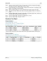
Страница 335: ...ested Step 7 Optional Repeat steps 1 through 6 through 6 for settings group 1 2 and 3 Step 8 Optional Repeat steps 1 through 7 for 27P 2 27P 3 and 27P 4 Functional Test Report Pickup Verification Pick...

Страница 336: ...58 4 9424200996 Phase Undervoltage 27P Test BE1 11m...

Страница 337: ...ar to compile BESTlogicPlus Upload BESTlogicPlus settings by selecting Upload Logic to Device from the Communication pull down menu Operational settings can be sent by selecting Upload Settings to Dev...

Страница 338: ...p 6 Slowly increase the A phase voltage until OUT2 closes and record the pickup Verify that there is a 59P 1 A target on the front panel display Slowly decrease the A phase voltage until OUT2 opens an...

Страница 339: ...phase being tested Step 7 Optional Repeat steps 1 through 6 for settings group 1 2 and 3 Step 8 Optional Repeat steps 1 through 7 for 59P 2 Functional Test Report Pickup Verification Pickup Setting Ra...

Страница 340: ...59 4 9424200996 Phase Overvoltage 59P Test BE1 11m...

Страница 341: ...ar to compile BESTlogicPlus Upload BESTlogicPlus settings by selecting Upload Logic to Device from the Communication pull down menu Operational settings can be sent by selecting Upload Settings to Dev...

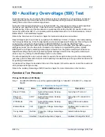
Страница 342: ...C phase and C16 neutral Step 6 Slowly increase the A phase voltage until OUT2 closes around 265 volts 150 Vac nominal 115 V 3V0 pickup setting and record the pickup Verify that there is a 59X 1 3V0 t...

Страница 343: ...targets Table 60 4 Operational Settings V1 Mode Setting Value BESTCOMSPlus Screen Description Phase VT Ratio 1 System Parameters Sensing Transformers Sets phase VT ratio to 1 Phase VT Connection 4W Y...

Страница 344: ...V 75 Vac on test set as listed in Table 60 5 Record the results Step 8 Optional Repeat steps 1 through 7 for the B phase and C phase voltage inputs Step 9 Optional Repeat steps 1 through 8 for setting...

Страница 345: ...3 BESTlogicPlus Settings V2 Mode Step 3 Use BESTCOMSPlus to open the Protection Voltage Overvoltage 59X 1 screen and send the first row of test settings in Table 60 8 to the BE1 11m Table 60 8 Pickup...

Страница 346: ...phase and C16 neutral Step 4 Step the voltage up to 130 volts Measure the time delay and record the result Step 5 Repeat step 4 for the 5 000 ms and 10 000 ms time delay settings of Table 60 9 Record...

Страница 347: ...get Step 7 Verify the pickup and dropout accuracy at 70 Vac for a pickup setting of 75 V and 25 Vac for a pickup setting of 30 V as listed in Table 60 11 Record the results Step 8 Optional Repeat step...

Страница 348: ...de Vx Third Harmonic Protection Voltage Overvoltage 59X 1 Enables 59X 1 function for Vx Third Harmonic mode Timing Mode Definite Protection Voltage Overvoltage 59X 1 Selects definite timings 59X 1 3RD...

Страница 349: ...Vx Third Harmonic Mode Pickup Setting Time Delay 125 V 2 000 ms 125 V 5 000 ms 125 V 10 000 ms Step 2 Prepare to monitor the 59X 1 timings Timing accuracy is verified by measuring the elapsed time be...

Страница 350: ...0 78 0 25 2 75 6 25 7 77 1 P F Dropout range is calculated from the pickup setting and may need adjusted based on actual pickup Timing Verification V1 Mode Time Delay Range 50 to 600 000 ms Timing Ac...

Страница 351: ...ge 50 to 600 000 ms Timing Accuracy 0 5 or 2 cycles whichever is greater Step Time Delay Setting Low Actual Timing High Pass Fail 4 2 000 ms 1 968 ms 2 032 ms P F 5 5 000 ms 4 968 ms 5 032 ms P F 5 10...

Страница 352: ...60 12 9424200996 Auxiliary Overvoltage 59X Test BE1 11m...

Страница 353: ...electing Upload Logic to Device from the Communication pull down menu Operational settings can be sent by selecting Upload Settings to Device from the Communication pull down menu or by clicking the S...

Страница 354: ...equency of the applied voltage until OUT2 closes and record the pickup Verify that there is an 81 1 Over target on the front panel display Slowly decrease the frequency until OUT2 opens and record the...

Страница 355: ...6 Slowly decrease the frequency of the applied voltage until OUT2 closes and record the pickup Verify that there is an 81 1 Under target on the front panel display Slowly increase the frequency until...

Страница 356: ...Mode Rate of Change Protection Frequency 81 1 Enables 81 1 function for Rate of Change mode Source Phase VT Protection Frequency 81 1 Sets source to Phase VT Pickup 10 Hz sec Protection Frequency 81 1...

Страница 357: ...from a low to high frequency does not cause an operation Step 12 Optional Repeat steps 1 through 11 for settings group 1 2 and 3 Step 13 Optional Repeat steps 1 through 12 for 81 2 81 3 and 81 4 Time...

Страница 358: ...n 1 volt increments repeating the sweep test after each reduction until OUT2 does not operate Inhibit should occur at 24 volts negative sequence Record the result Step 5 Set the Negative Sequence Inhi...

Страница 359: ...from the pickup setting and may need adjusted based on actual pickup Time Delay Verification Time Delay Range 0 to 600 000 ms Timing Accuracy 0 5 or 1 cycle whichever is greater 3 cycles recognition...

Страница 360: ...61 8 9424200996 Frequency 81 Test BE1 11m...

Страница 361: ...o compile BESTlogicPlus Upload BESTlogicPlus settings by selecting Upload Logic to Device from the Communication pull down menu Operational settings can be sent by selecting Upload Settings to Device...

Страница 362: ...phase Note that IA IB or IC can be used for this test Test is conducted on IA Step 6 Slowly decrease the A phase current until OUT2 closes and record pickup Verify the 37 1 target on the front panel d...

Страница 363: ...Range 0 5 to 100 A for 5A sensing 0 1 to 20 A for 1A sensing Pickup Accuracy 2 or 50 mA whichever is greater for 5A sensing 2 or 10 mA whichever is greater for 1A sensing Dropout should occur between...

Страница 364: ...62 4 9424200996 Instantaneous Undercurrent 37 Test BE1 11m...

Страница 365: ...Plus Upload BESTlogicPlus settings by selecting Upload Logic to Device from the Communication pull down menu Operational settings can be sent by selecting Upload Settings to Device from the Communicat...

Страница 366: ...s a 50 1 A target on the front panel display Slowly decrease the applied current until OUT2 opens and record the dropout Step 7 Repeat step 6 for the middle and high range pickup settings for your sen...

Страница 367: ...urce for protection systems equipped with two sets of CTs In step 3 replace D1 with F1 D2 with F2 etc Pickup Verification 3I0 Mode Step 1 Use BESTCOMSPlus to send the operational settings in Table 63...

Страница 368: ...t steps 1 through 8 for 50 2 50 3 50 4 50 5 and 50 6 Step 10 Optional Repeat steps 1 through 9 with CT Circuit 2 as the source for protection systems equipped with two sets of CTs In step 5 replace D1...

Страница 369: ...us programmable logic shown in Figure 63 3 Blocking is disabled OUT1 closes for 50 1 Trip OUT2 closes for 50 1 Pickup Fault recording is enabled Figure 63 3 BESTlogicPlus Settings I2 Mode Step 3 Use B...

Страница 370: ...tings group 0 Table 63 9 Timing Test Settings I2 Mode Pickup Setting Time Delay 0 5 A 2 000 ms 0 5 A 5 000 ms 0 5 A 10 000 ms Step 2 Prepare to monitor the 50 1 timings Timing accuracy is verified by...

Страница 371: ...ault recording is enabled Figure 63 4 BESTlogicPlus Settings IG Mode Step 3 Use BESTCOMSPlus to open the Protection Current Instantaneous Overcurrent 50 1 screen and send the low range test settings m...

Страница 372: ...round current up to 0 55 A Measure the time delay and record the result Step 5 Repeat step 4 for the 5 000 ms and 10 000 ms time delay settings of Table 63 12 Record the results Step 6 Optional Repeat...

Страница 373: ...0 575 A 0 465 A 0 495 A P F 7 5 0 A 5A CT 4 85 A 5 15 A 4 65 A 4 95 A P F 7 20 0 A 5A CT 19 4 A 20 6 A 18 6 A 19 8 A P F 6 0 1 A 1A CT 0 085 A 0 115 A 0 093 A 0 099 A P F 7 1 0 A 1A CT 0 97 A 1 03 A...

Страница 374: ...ss Fail 4 2 000 ms 1 942 ms 2 058 ms P F 5 5 000 ms 4 927 ms 5 073 ms P F 5 10 000 ms 9 902 ms 10 098 ms P F Pickup Verification IG Mode Pickup Setting Range 0 5 to 150 A for 5A sensing 0 1 to 30 A fo...

Страница 375: ...ode Time Delay Range 0 to 60 000 ms Timing Accuracy 0 5 or cycle whichever is greater 3 cycles max for currents 1 5 x pickup Step Time Delay Setting Low Actual Timing High Pass Fail 4 2 000 ms 1 942 m...

Страница 376: ...63 12 9424200996 Instantaneous Overcurrent 50 Test BE1 11m...

Страница 377: ...g Upload Settings to Device from the Communication pull down menu or by clicking the Send Settings button on the toolbar The actual operating time of an output contact is equal to the recognition time...

Страница 378: ...hould be no operation Step 6 Repeat step 3 with the delay timer set at 200 ms and 300 ms Record the results The following tests are for Current Supervised BE1 11m trip initiates Any or all BE1 11m tri...

Страница 379: ...kup current above 2 A to phase A for at least 100 ms A 50BF Trip should occur Use BESTCOMSPlus to retrieve an SER report and verify that a 50BF Trip was logged 100 milliseconds 0 5 1 cycles maximum fo...

Страница 380: ...r Record the result Step 13 Optional Repeat steps 1 through 12 for the B and C phase elements Note Set 50 1 mode to IB for B phase and IC for C phase Step 14 Optional Repeat steps 7 through 13 with CT...

Страница 381: ...Plus Upload BESTlogicPlus settings by selecting Upload Logic to Device from the Communication pull down menu Operational settings can be sent by selecting Upload Settings to Device from the Communicat...

Страница 382: ...he pickup Verify that there is a 51 1 A target on the front panel display Slowly decrease the applied current until OUT2 opens and record the dropout Step 7 Repeat step 6 for the middle and high range...

Страница 383: ...for the B phase and C phase current inputs Note Be sure to enable proper target for each phase being tested Step 7 Optional Repeat steps 1 through 6 for settings group 1 2 and 3 Step 8 Optional Repeat...

Страница 384: ...ickup Fault recording is enabled Figure 65 2 BESTlogicPlus Settings 3I0 Mode Step 3 Use BESTCOMSPlus to open the Protection Current Inverse Overcurrent 51 1 screen and send the low range test settings...

Страница 385: ...mings Timing accuracy is verified by measuring the elapsed time between a sensing current change and OUT1 closing Step 3 Connect a current source to BE1 11m terminals D1 and D2 A phase Step 4 Using th...

Страница 386: ...grammable logic shown in Figure 65 3 Blocking is disabled OUT1 closes for 51 1 Trip OUT2 closes for 51 1 Pickup Fault recording is enabled Figure 65 3 BESTlogicPlus Settings I2 Mode Step 3 Use BESTCOM...

Страница 387: ...5 replace D1 with F1 D2 with F2 etc Timing Verification I2 Mode Step 1 Use BESTCOMSPlus to open the Protection Current Inverse Overcurrent 51 1 screen and send the test settings in Table 65 11 to the...

Страница 388: ...s IND GND target for 51 1 Step 2 Use BESTCOMSPlus to configure the BESTlogicPlus programmable logic shown in Figure 65 4 Blocking is disabled OUT1 closes for 51 1 Trip OUT2 closes for 51 1 Pickup Faul...

Страница 389: ...ttings IG Mode Pickup Setting Time Curve 0 5 A 5 A sensing 0 1 A 1 A sensing I2 Step 2 Prepare to monitor the 51 1 timings Timing accuracy is verified by measuring the elapsed time between a sensing c...

Страница 390: ...12 50 A 1 A 0 5 0 20 A 0 50 A 2 50 A 5 0 0 20 A 0 50 A 2 50 A 9 9 0 20 A 0 50 A 2 50 A SEF 0 5 0 20 A 0 50 A 0 80 A 5 0 0 20 A 0 50 A 0 80 A 9 9 0 20 A 0 50 A 0 80 A Functional Test Report Pickup Ver...

Страница 391: ...40 sec P F 4 0 5 I2 12 50 A 0 100 sec 0 150 sec P F 4 5 0 I2 1 00 A 4 204 sec 4 647 sec P F 4 5 0 I2 2 50 A 1 798 sec 1 988 sec P F 4 5 0 I2 12 50 A 0 944 sec 1 044 sec P F 4 9 9 I2 1 00 A 8 300 sec 9...

Страница 392: ...sec 0 240 sec P F 4 0 5 I2 12 50 A 0 100 sec 0 150 sec P F 4 5 0 I2 1 00 A 4 204 sec 4 647 sec P F 4 5 0 I2 2 50 A 1 798 sec 1 988 sec P F 4 5 0 I2 12 50 A 0 944 sec 1 044 sec P F 4 9 9 I2 1 00 A 8 30...

Страница 393: ...r is greater Step Time Dial Time Curve Applied Current Low Actual Timing High Pass Fail 4 0 5 I2 3 00 A 0 444 sec 0 491 sec P F 4 0 5 I2 7 50 A 0 190 sec 0 240 sec P F 4 0 5 I2 27 00 A 0 094 sec 0 174...

Страница 394: ...0 465 A 0 495 A P F 7 0 8 A SEF sensing 0 63 A 0 97 A 0 074 A 0 792 A P F Dropout range is calculated from the pickup setting and may need adjusted based on actual pickup Timing Verification IG Mode...

Страница 395: ...e 0 0 to 9 9 Timing Accuracy 5 or 1 cycles whichever is greater Step Time Dial Time Curve Applied Current Low Actual Timing High Pass Fail 4 0 5 I2 0 20 A 0 444 sec 0 491 sec P F 4 0 5 I2 0 50 A 0 190...

Страница 396: ...65 16 9424200996 Inverse Overcurrent 51 Test BE1 11m...

Страница 397: ...he Communication pull down menu Operational settings can be sent by selecting Upload Settings to Device from the Communication pull down menu or by clicking the Send Settings button on the toolbar The...

Страница 398: ...t Phase Differential 87 Sets the 1st slope of the restraint characteristic to 20 2nd Slope Pickup MOT 3 00 Protection Current Phase Differential 87 The 2nd slope is active when the measured maximum re...

Страница 399: ...cord the pickup This should occur at 2 40 A 0 05 A Verify that there is an 87A target on the front panel display Step 14 To test the Restraint Slope 2 setting connect two balanced three phase current...

Страница 400: ...nt Slope 2 40 Protection Current Phase Differential 87 Sets the 2nd slope of the restraint characteristic to 40 Time Delay ms 100 Protection Current Phase Differential 87 Sets the trip time delay to 1...

Страница 401: ...ecrease the A phase current in CT circuit 1 or 2 until OUT2 closes and record the pickup This should occur at 5 32 A 0 11 A Verify that there is an 87A target on the front panel display Step 18 Option...

Страница 402: ...A 0 68 A P F 8 9 MRPU 0 30 A 0 25 A 0 35 A 0 28 A 0 39 A P F 11 Slope 1 3 67 A 3 59 A 3 74 A N A N A N A P F 13 Slope 1 2 46 A 2 41 A 2 51 A N A N A N A P F 15 Slope 2 8 25 A 8 09 A 8 42 A N A N A N...

Страница 403: ...mmunication pull down menu or by clicking the Send Settings button on the toolbar The actual operating time of an output contact is equal to the recognition time plus the time delay setting accuracy p...

Страница 404: ...neutral Connect a variable ac current source to terminals D1 A phase polarity and D2 A phase non polarity Step 3 Set A phase current in phase with the voltage and slowly increase the current from 0 am...

Страница 405: ...Protection chapter for operating details Step 6 Optional Repeat steps 1 through 5 for settings group 1 2 and 3 Step 7 Optional Repeat steps 1 through 6 with CT2 as the bus CT selection for protection...

Страница 406: ...splay Increase A phase current until OUT2 opens and record the reset Pickup will occur within 3 of the 32 1 pickup setting 500 watts 5 amps 100 volts 180 degrees I lag E Step 4 With the BE1 11m picked...

Страница 407: ...uracy 3 or 2 W whichever is greater Reset should occur between 95 99 of the actual pickup value Step Setting Low Pickup High Low Dropout High Pass Fail 3 500 W 485 0 W 515 0 W 475 0 W 495 0 W P F 5 25...

Страница 408: ...67 6 9424200996 Power 32 Test BE1 11m...

Страница 409: ...on the toolbar to compile BESTlogicPlus Upload BESTlogicPlus settings by selecting Upload Logic to Device from the Communication pull down menu Operational settings can be sent by selecting Upload Set...

Страница 410: ...y and D2 A phase non polarity Step 5 Set A phase current to lag the voltage by 90 degrees and slowly increase the current from 0 amps until OUT2 closes and record the pickup Verify the 40Q target on t...

Страница 411: ...Optional Repeat steps 1 through 5 for settings group 1 2 and 3 Functional Test Report Pickup Verification Pickup Setting Range 1 to 6 000 var for 5A sensing 1 to 1 200 var for 1A sensing Pickup Accur...

Страница 412: ...68 4 9424200996 Loss of Excitation Reverse Var Based 40Q Test BE1 11m...

Страница 413: ...TlogicPlus settings by selecting Upload Logic to Device from the Communication pull down menu Operational settings can be sent by selecting Upload Settings to Device from the Communication pull down m...

Страница 414: ...hould happen at IA VA cos 1 0 5 60 0 66 0 49 0 51 PF leading Decrease the IA angle until OUT1 opens and record the reset Reset the target Step 7 Rotate the IA angle in the lagging direction until a pi...

Страница 415: ...for settings group 1 2 and 3 Functional Test Report Pickup Verification Table 2 Row 1 Pickup Setting Range 0 05 to 0 99 leading lagging Pickup Accuracy 0 01 Step Pickup Setting Low Actual Pickup High...

Страница 416: ...ng Verification Time Delay Range 0 ms or 50 to 600 000 ms Timing Accuracy 0 5 or 2 cycles whichever is greater Step Time Delay Setting Low Actual Timing High Pass Fail 4 60 000 ms 59 700 ms 60 300 ms...

Страница 417: ...d on the toolbar to compile BESTlogicPlus Upload BESTlogicPlus settings by selecting Upload Logic to Device from the Communication pull down menu Operational settings can be sent by selecting Upload S...

Страница 418: ...Overload pickup to 1 Max Emergency Thermal Capacity 0 Protection Thermal Thermal Curve 49TC Sets Max Emergency Thermal Capacity to 0 Running Cool Time Constant 1 Protection Thermal Thermal Curve 49TC...

Страница 419: ...ndamental component of current in pickup k constant used to determine additional heating from negative sequence current in pickup The Standard Curve Timing is calculated in Equation 70 3 88 744132 2 2...

Страница 420: ...seconds because TC starts at 12 Reference Equation 70 3 The thermal capacity 12 to 100 can be monitored at Metering Motor Motor Meter on the front panel display Verify that there is a 49TC target on...

Страница 421: ...unications Defines the Remote Module ID RTD 1 Type 100 Platinum Programmable Inputs Remote RTD RTD Type Selection Simulates a 100 Platinum Resistor for RTD 1 RTD 1 Enabled Programmable Inputs Remote R...

Страница 422: ...erance of the 120 resistor The value of RTD 1 1 changes according to the value of the resistor The RTD Bias Curve graph in BESTCOMSPlus is used to determine the starting TC It is determined that the s...

Страница 423: ...l Thermal Curve 49TC Sets Standard Curve Time Dial to 10 K 0 Protection Thermal Thermal Curve 49TC Sets K to 0 Overload 1 Protection Thermal Thermal Curve 49TC Sets Overload pickup to 1 Max Emergency...

Страница 424: ...T4 Starting closes Measure and record the time from when current is applied until OUT1 Tripped closes and the thermal capacity reaches 100 The expected timing is 11 52 seconds per the Overload Charact...

Страница 425: ...les whichever is greater Step Time Dial Applied Current Low Actual Timing High Pass Fail 17 10 10 A 68 818 sec 76 062 sec P F Timing Verification Standard Curve with RTD Biasing Time Dial Range 1 to 2...

Страница 426: ...70 10 9424200996 Thermal Curve 49TC Test BE1 11m...

Страница 427: ...ting Upload Logic to Device from the Communication pull down menu Operational settings can be sent by selecting Upload Settings to Device from the Communication pull down menu or by clicking the Send...

Страница 428: ...ply 10 Aac three phase current simulate motor starting Verify that OUT4 Starting is closed during timing Measure and record the time from when current is applied until OUT1 Trip closes The expected ti...

Страница 429: ...ogic to Device from the Communication pull down menu Operational settings can be sent by selecting Upload Settings to Device from the Communication pull down menu or by clicking the Send Settings butt...

Страница 430: ...and D5 and D6 IC Step 5 Apply 10 Aac three phase current for approximately one minute simulate motor starting Note that this is the first start Verify that OUT1 Starting closes and OUT2 Stopped opens...

Страница 431: ...ting opens and OUT2 Stopped closes Verify that OUT3 Start Blocked remains closed Step 9 Wait approximately three minutes for timing to complete Stop the timer when OUT4 Start Block Removed closes and...

Страница 432: ...72 4 9424200996 Starts per Time Interval 66 Test BE1 11m...

Страница 433: ...s by selecting Upload Logic to Device from the Communication pull down menu Operational settings can be sent by selecting Upload Settings to Device from the Communication pull down menu or by clicking...

Страница 434: ...hat OUT3 Start Blocked opens when OUT4 Start Blocked Removed closes Step 9 Apply 10 Aac three phase current simulate motor starting and verify that a start is possible Remove three phase current Allow...

Страница 435: ...s Note that OUT3 Start Blocked opens when OUT4 Start Blocked Removed closes Step 18 Apply 10 Aac three phase current simulate motor starting and verify that a start is possible Remove three phase curr...

Страница 436: ...73 4 9424200996 Restart Inhibit Test BE1 11m...

Страница 437: ...STlogicPlus settings by selecting Upload Logic to Device from the Communication pull down menu Operational settings can be sent by selecting Upload Settings to Device from the Communication pull down...

Страница 438: ...formed within 25 seconds of step 5 the indicator will stop flashing and the 43 1 button will have to be selected again Step 6 Click on the 43 1 button a second time to operate it After clicking Yes th...

Страница 439: ...and 5 to change the state of the 43 1 switch to OFF Verify that OUT1 contact opens and remains open Step 8 Optional Repeat steps 1 through 7 for 43 2 43 3 43 4 and 43 5 Step 9 Optional Repeat steps 1...

Страница 440: ...74 4 9424200996 Virtual Control Switches 43 Test BE1 11m...

Страница 441: ...icPlus settings by selecting Upload Logic to Device from the Communication pull down menu Operational settings can be sent by selecting Upload Settings to Device from the Communication pull down menu...

Страница 442: ...flash Note If step 6 is not performed within 25 seconds of step 5 the indicator will stop flashing and the 43 1 button will have to be selected again Step 6 Click on the 43 1 button a second time to o...

Страница 443: ...Target Enabled Target Configuration Targets screen Enables 62 1 target Step 2 Step 4 supplies the 62 1 timer with a momentary initiate input by pulsing the 43 1 switch from an OFF state to an ON state...

Страница 444: ...y 1 T1 15 000 ms Control Logic Timers 62 Sets 62 1 pickup time delay to 15 000 ms 62 1 Time Delay 2 T2 20 000 ms Control Logic Timers 62 Sets 62 1 dropout time delay to 20 000 ms 43 1 Mode Pulse Contr...

Страница 445: ...es the timing relationship of the 43 1 switch and 62 1 timer Figure 75 5 One Shot Retriggerable Mode Step 8 Optional Repeat steps 1 through 7 for 62 1 62 2 62 3 62 4 62 5 62 6 62 7 and 62 8 Step 9 Opt...

Страница 446: ...ed again Step 5 Click on the 43 1 button a second time to operate it After clicking Yes the On or Off indicator previous state will stop flashing and the On or Off indicator current new state will lig...

Страница 447: ...43 Sets 43 1 to Pulse mode 43 2 Mode Pulse Control Virtual Control Switches 43 Sets 43 2 to Pulse mode 62 1 Target Enabled Target Configuration Targets screen Enables 62 1 target Step 2 Use BESTCOMSP...

Страница 448: ...30 seconds total elapsed time before beginning step 8 Step 8 Using the front panel display navigate to Metering Control Virtual Switches Highlight the second switch 43 2 and press the Right key on the...

Страница 449: ...5 8 Latched Mode Functional Test Report Function Pass Fail Pickup Dropout Mode P F One Shot Non Retriggerable Mode P F One Shot Retriggerable Mode P F Oscillator Mode P F Integrating Timer Mode P F La...

Страница 450: ...75 10 9424200996 Logic Timers 62 Test BE1 11m...

Страница 451: ...ick the Save button located on the toolbar to compile BESTlogicPlus Upload BESTlogicPlus settings by selecting Upload Logic to Device from the Communication pull down menu Operational settings can be...

Страница 452: ...This verifies that the 86 1 position is stored in non volatile memory Remove voltage from IN1 Step 7 Connect power supply to IN2 terminals Step 8 Apply voltage to IN2 Verify that OUT1 opens and remai...

Страница 453: ...ion pull down menu or by clicking the Send Settings button on the toolbar The actual operating time of an output contact is equal to the recognition time plus the time delay setting accuracy plus 6 mi...

Страница 454: ...uired The green selection LED will begin to flash Within 25 seconds click on the CLOSE button a second time to operate it The green selection LED will stop flashing and the close status LED will light...

Страница 455: ...ure that the contact will stay closed for at least 200 milliseconds See the Contact Inputs and Outputs chapter for additional information on that function Also a Set Priority Latch in BESTlogic Plus c...

Страница 456: ...s home page of the web page interface Four on the Metering Explorer Device Info screen of BESTCOMSPlus Features How many overcurrent elements does the BE1 11m have available The BE1 11m has six instan...

Страница 457: ...ration of equipment main or auxiliary Proper alarming to SCADA and or targeting If you do not get the results that you expect from the BE1 11m first check the programmable settings for the appropriate...

Страница 458: ...llation Step 2 Open the Windows Device Manger as shown in Figure 79 2 Right click on BE1 11 or Unknown Device under Other Devices and select Properties Figure 79 2 Device Manager Step 3 In the Propert...

Страница 459: ...1 11 Properties Step 4 Select Browse My Computer for Driver Software as shown in Figure 79 4 Figure 79 4 Update Driver Software BE1 11 Step 5 Click Browse and navigate to C Program Files Basler Electr...

Страница 460: ...g BE1 11m Figure 79 5 Update Driver Software BE1 11 Step 6 If a Windows Security window Figure 79 6 appears click Install Figure 79 6 Windows Security Step 7 The window in Figure 79 7 appears if drive...

Страница 461: ...uld be terminated To close front panel access immediately press the Reset button while any menu screen is displayed The BE1 11m should flash Read Only on the LCD screen to indicate access through the...

Страница 462: ...correct Step 4 Verify that the current sensing transformers are correct and properly installed Incorrect Display of Voltage Step 1 Verify that all wiring is properly connected Refer to the Typical Co...

Страница 463: ...hts steadily when neither expression is true but latched targets exist When resetting a target the Trip LED will not turn off if the fault is still present The truth table of Table 79 1 serves as an a...

Страница 464: ...79 8 9424200996 Troubleshooting BE1 11m...

Страница 465: ...0 displayed Metered Voltage Values and Accuracy 3 wire Range 50 to 250 Vac 4 wire Range 50 to 250 Vac Auxiliary Range 25 to 125 Vac Phase Auxiliary Accuracy 0 5 of reading or 0 1 of full range whichev...

Страница 466: ...r is greater Reset Inhibit Ratio 102 1 Timing Mode Definite Timing Setting Range 50 to 600 000 ms Accuracy 0 5 or 2 cycles whichever is greater Inverse Timing Setting Range 0 to 9 9 Accuracy 5 or 2 cy...

Страница 467: ...Range 1 to 1 200 var Accuracy 3 or 2 var whichever is greater Dropout 93 to 99 of the actual pickup value Time Delay Setting Range 1 to 600 000 ms Accuracy 0 5 or 2 cycles whichever is greater 46 Nega...

Страница 468: ...hever is greater 1 Ampere CT 2 or 10 mA whichever is greater SEF Pickup Setting of 0 01 to 4 99 A 2 5 4 5 mA SEF Pickup Setting of 5 to 7 5 A 5 4 5 mA 3I0 I1 I2 Accuracy 5 Ampere CT 3 or 75 mA whichev...

Страница 469: ...hever is greater 1 Ampere CT 2 or 10 mA whichever is greater SEF 2 5 2 5 mA 3I0 I1 I2 Accuracy 5 Ampere CT 3 or 75 mA whichever is greater 1 Ampere CT 3 or 15 mA whichever is greater Unbalanced Accura...

Страница 470: ...ccuracy 2 or 1 V whichever is greater Dropout Pickup Ratio 98 1 Timing Mode Definite Timing Setting Range 50 to 600 000 ms Accuracy 0 5 or 2 cycles whichever is greater Inverse Timing Setting Range 0...

Страница 471: ...l voltage Accuracy 0 5 or 1 V whichever is greater Time Delay Setting Range 0 to 600 000 ms Accuracy 0 5 or 1 cycle whichever is greater plus recognition time Recognition time 2 cycles for 0 57 pickup...

Страница 472: ...acy 0 5 or 3 cycles Time Between Starts Setting Range 0 to 7 200 min Accuracy 0 5 or 3 cycles Automatic Setting Group Characteristics Number of Setting Groups 4 Control Modes Automatic Cold Load Picku...

Страница 473: ...Optional IA2 F1 F2 IB2 F3 F4 IC2 F5 F6 IN2 F7 F8 Phase AC Voltage Inputs Continuous Rating 300 V Line to Line One Second Rating 600 V Line to Neutral Burden 1 VA 300 Vac Terminals VA C13 VB C14 VC C1...

Страница 474: ...C10 OUT 6 E11 E12 OUT 7 E9 E10 OUT 8 E7 E8 OUT A C11 C12 Contact Sensing Inputs Maximum Input Voltage The maximum input voltages are the highest voltage for each power supply range listed under the P...

Страница 475: ...dback then one or more BESTlogicPlus update rate delays must be included to calculate the worst case delay An example of feedback is logic outputs driving logic inputs For more information see BESTlog...

Страница 476: ...ront panel B type USB connector provides local communication with a PC operating BESTCOMSPlus software Compatible with USB 2 0 specification Data Transfer Speed 12 MB s Full Speed RS 485 Rear panel RS...

Страница 477: ...ing Guidance for Damp Heat Tests IEC 60255 4 Single Input Energizing Quantity Measuring Relays with Dependent Specified Time IEC 60255 5 Electrical Insulation Tests for Electrical Relays Dielectric Te...

Страница 478: ...ess power has been switched off or the area is known to be non hazardous CSA Certification This product was tested and has met the certification requirements for industrial control equipment Standards...

Страница 479: ...9424200996 80 15 BE1 11m Specifications IEC 61850 Certification KEMA certified per IEC 61850 Certificate Level A Physical Weight 5 1 lb 2 3 kg IP Class IP50 Case Size Refer to the Mounting chapter...

Страница 480: ...80 16 9424200996 Specifications BE1 11m...

Страница 481: ...ues and Accuracy 3 wire Range 50 to 250 Vac 4 wire Range 50 to 250 Vac Auxiliary Range 25 to 125 Vac Phase Auxiliary Accuracy 1 of reading or 0 2 of full range whichever is greater at 77 F 25 C V1 V2...

Страница 482: ...s greater Reset Inhibit Ratio 102 1 Timing Mode Definite Timing Setting Range 50 to 600 000 ms Accuracy 1 5 or 4 cycles whichever is greater Inverse Timing Setting Range 0 to 9 9 Accuracy 8 or 4 cycle...

Страница 483: ...T Setting Range 1 to 1 200 var Accuracy 4 or 4 var whichever is greater Dropout 93 to 99 of the actual pickup value Time Delay Setting Range 1 to 600 000 ms Accuracy 1 5 or 4 cycles whichever is great...

Страница 484: ...l pickup value 3Phase IA IB IC IG Accuracy 5 Ampere CT 4 or 50 mA whichever is greater 1 Ampere CT 4 or 10 mA whichever is greater SEF Pickup Setting of 0 01 to 4 99 A 5 4 5 mA SEF Pickup Setting of 5...

Страница 485: ...mA whichever is greater 1 Ampere CT 4 or 10 mA whichever is greater SEF 5 2 5 mA 3I0 I1 I2 Accuracy 5 Ampere CT 3 or 75 mA whichever is greater 1 Ampere CT 3 or 15 mA whichever is greater Unbalanced A...

Страница 486: ...150 V Accuracy 2 or 1 V whichever is greater Dropout Pickup Ratio 98 1 Timing Mode Definite Timing Setting Range 50 to 600 000 ms Accuracy 1 5 or 4 cycles whichever is greater Inverse Timing Setting...

Страница 487: ...f nominal voltage Accuracy 0 5 or 1 V whichever is greater Time Delay Setting Range 0 to 600 000 ms Accuracy 0 5 or 1 cycle whichever is greater plus recognition time Recognition time 2 cycles for 0 5...

Страница 488: ...a current of 1 05 times the pickup setting Restart Inhibit Protection Restart Delay Setting Range 0 to 7 200 min Accuracy 1 5 or 3 cycles Time Between Starts Setting Range 0 to 7 200 min Accuracy 1 5...

Страница 489: ...le time function and four Table Curve functions can be selected Characteristic curves for the inverse and definite time functions are defined by the following equations and comply with IEEE Std C37 11...

Страница 490: ...797 0 21359 1 1 5625 0 028 0 875 F Fixed Time 0 1 0 0 0 1 46 K Factor 0 0 2 0 028 100 P User Programmable 0 to 600 0 to 25 0 to 1 0 5 to 2 5 0 028 0 to 30 T1 User Table 1 n a n a n a n a n a n a T2 Us...

Страница 491: ...r n a P User Programmable n a T1 T2 T3 T4 User Tables n a Time Dial Setting Cross Reference Although the time characteristic curve shapes have been optimized for each BE1 11m time dial settings of Bas...

Страница 492: ...3 4 4 2 5 0 5 8 6 7 7 7 8 6 9 7 S2 GE IAC 55 0 2 1 0 2 0 3 1 4 0 4 9 6 1 7 2 8 1 8 9 9 8 n a I1 ABB CO 8 0 3 0 7 1 5 2 3 3 2 4 0 5 0 5 8 6 8 7 6 8 7 n a I2 GE IAC 51 0 6 1 0 1 9 2 7 3 7 4 8 5 7 6 8 8...

Страница 493: ...sponds to 1 per unit current in the generator When curve 46 is selected the BE1 11m changes the range of the allowed time dial to 1 to 99 instead of the time dial range of 0 1 to 9 9 for all the other...

Страница 494: ...82 6 9424200996 Time Curve Characteristics BE1 11m Figure 82 1 Time Characteristic Curve S1 Short Inverse Similar to ABB CO 2...

Страница 495: ...9424200996 82 7 BE1 11m Time Curve Characteristics Figure 82 2 Time Characteristic Curve S2 Short Inverse Similar To GE IAC 55...

Страница 496: ...82 8 9424200996 Time Curve Characteristics BE1 11m Figure 82 3 Time Characteristic Curve A Standard Inverse BS 142...

Страница 497: ...9424200996 82 9 BE1 11m Time Curve Characteristics Figure 82 4 Time Characteristic Curve A1 Inverse IEC 60255 151 Ed 1...

Страница 498: ...82 10 9424200996 Time Curve Characteristics BE1 11m Figure 82 5 Time Characteristic Curve I1 Inverse Time Similar to ABB CO 8...

Страница 499: ...9424200996 82 11 BE1 11m Time Curve Characteristics Figure 82 6 Time Characteristic Curve I2 Inverse Time Similar to GE IAC 51...

Страница 500: ...82 12 9424200996 Time Curve Characteristics BE1 11m Figure 82 7 Time Characteristic Curve M Moderately Inverse Similar to ABB CO 7...

Страница 501: ...acteristics Figure 82 8 Time Characteristic Curve D1 Moderately Inverse IEC 60255 151 Ed 1 0 01 0 10 1 00 10 00 100 00 1000 00 1 10 100 MULTIPLES OF PICKUP TIME IN SECONDS 9 9 9 0 8 0 7 0 6 0 5 0 4 0...

Страница 502: ...82 14 9424200996 Time Curve Characteristics BE1 11m Figure 82 9 Time Characteristic Curve L1 Long Inverse Similar to ABB CO 5...

Страница 503: ...9424200996 82 15 BE1 11m Time Curve Characteristics Figure 82 10 Time Characteristic Curve L2 Long Inverse Similar To GE IAC 66...

Страница 504: ...82 16 9424200996 Time Curve Characteristics BE1 11m Figure 82 11 Time Characteristic Curve G Long Time Inverse BS 142...

Страница 505: ...9424200996 82 17 BE1 11m Time Curve Characteristics Figure 82 12 Time Characteristic Curve V1 Very Inverse Similar to ABB CO 9...

Страница 506: ...82 18 9424200996 Time Curve Characteristics BE1 11m Figure 82 13 Time Characteristic Curve V2 Very Inverse Similar to GE IAC 53...

Страница 507: ...9424200996 82 19 BE1 11m Time Curve Characteristics Figure 82 14 Time Characteristic Curve B Very Inverse BS 142...

Страница 508: ...82 20 9424200996 Time Curve Characteristics BE1 11m Figure 82 15 Time Characteristic Curve B1 Very Inverse IEC 60255 151 Ed 1...

Страница 509: ...aracteristics Figure 82 16 Time Characteristic Curve E3 Very Inverse IEC 60255 151 Ed 1 0 01 0 10 1 00 10 00 100 00 1000 00 1 10 100 MULTIPLES OF PICKUP TIME IN SECONDS 9 9 9 0 8 0 7 0 6 0 5 0 4 0 3 0...

Страница 510: ...82 22 9424200996 Time Curve Characteristics BE1 11m Figure 82 17 Time Characteristic Curve E1 Extremely Inverse Similar to ABB CO 11...

Страница 511: ...9424200996 82 23 BE1 11m Time Curve Characteristics Figure 82 18 Time Characteristic Curve E2 Extremely Inverse Similar to GE IAC 77...

Страница 512: ...82 24 9424200996 Time Curve Characteristics BE1 11m Figure 82 19 Time Characteristic Curve C Extremely Inverse BS 142...

Страница 513: ...9424200996 82 25 BE1 11m Time Curve Characteristics Figure 82 20 Time Characteristic Curve C1 Extremely Inverse IEC 60255 151 Ed 1...

Страница 514: ...ics BE1 11m Figure 82 21 Time Characteristic Curve F1 Extremely Inverse IEC 60255 151 Ed 1 0 01 0 10 1 00 10 00 100 00 1000 00 1 10 100 MULTIPLES OF PICKUP TIME IN SECONDS 9 9 9 0 8 0 7 0 6 0 5 0 4 0...

Страница 515: ...9424200996 82 27 BE1 11m Time Curve Characteristics Figure 82 22 Time Characteristic Curve D Definite Time Similar To ABB CO 6...

Страница 516: ...ic Curve NOTE Curves are shown as extending farther to the left than they will in practice Curves stop at pickup level For example if the user selects 5A FLC and a pickup setting of 0 5A the per unit...

Страница 517: ...dervoltage inverse time curve is defined by Equation 82 8 The undervoltage inverse time curve with default constants is shown in Figure 82 24 Equation 82 8 2 1 Equation 82 9 TT Time to trip when M 1 T...

Страница 518: ...30 9424200996 Time Curve Characteristics BE1 11m Figure 82 24 Undervoltage 27 Inverse Time Curve Default Constants 0 10 1 00 10 00 100 00 0 1 TIME IN SECONDS MULTIPLES OF PICKUP 9 9 9 8 7 6 5 4 3 2 1...

Страница 519: ...verse time curve with default constants is shown in Figure 82 25 Equation 82 10 2 1 Equation 82 11 TT Time to trip when M 1 TR Time to reset if BE1 11m is set for integrating reset when M 1 Otherwise...

Страница 520: ...Curve Characteristics BE1 11m Figure 82 25 Overvoltage 59 Inverse Time Curve Default Constants 0 10 1 00 10 00 100 00 1 1 1 1 2 1 3 1 4 1 5 1 6 1 7 1 8 1 9 2 TIME IN SECONDS MULTIPLES OF PICKUP 9 9 9...

Страница 521: ...rve mode The standard curve provides a Ieq 2 curve with a range of time dial settings that accommodate a wide range of motor timings The standard curve equation is shown in Equation 82 12 t TD 88 7441...

Страница 522: ...acteristics BE1 11m The standard curve is illustrated in Figure 82 26 Figure 82 26 49TC Standard Curve 0 1 1 10 100 1000 10000 0 2 4 6 8 10 12 14 TIME IN SECONDS Multiple of Overload Pickup T I M E D...

Страница 523: ...no greater than 95 of the thermal current pickup S SF FLA An internal hot to cold timer is initiated when the motor is stopped while in a hot state and the thermal capacity is less than 10 The motor...

Страница 524: ...s BE1 11m The IEC Curve is illustrated in Figure 82 27 Figure 82 27 49TC IEC Curve 0 1 1 10 100 1000 10000 100000 0 2 4 6 8 10 12 14 TIME IN SECONDS Multiple of Overload Pickup T I M E C O N S T A N T...

Страница 525: ...c range Firmware below 1 01 01 is not operational outside the ranges The label text of each analog input is customizable RTD Inputs The RTD module provides 12 user configurable RTD inputs for monitori...

Страница 526: ...e Figure 83 1 for RTD module overall dimensions All dimensions are shown in inches with millimeters in parenthesis Figure 83 1 RTD Module Overall Dimensions Connections RTD module connections are depe...

Страница 527: ...c dc and tolerates voltage over the range of 90 to 270 Vac or 90 to 300 Vdc The operating power inputs are not polarity sensitive Operating power terminals are listed in Table 83 1 Table 83 1 Operatin...

Страница 528: ...hown in Figure 83 4 When using the current input AIN V and AIN I must be tied together 7 8 9 10 11 12 13 14 15 16 17 18 19 20 21 22 23 24 25 26 27 28 29 30 31 32 33 34 35 36 48 47 46 45 44 43 42 41 40...

Страница 529: ...nnections External 2 wire RTD input connections are shown in Figure 83 5 Figure 83 6 shows external 3 wire RTD input connections Figure 83 5 External Two Wire RTD Input Connections AIN I AIN AIN V RTD...

Страница 530: ...f the following procedures to set up the RTD module It is assumed that the BE1 11m is already connected to the PC or network Procedure 1 The PC and BE1 11m are connected through a network or the PC is...

Страница 531: ...ings file for the RTD module click the Ethernet button under Device Discovery to scan for connected devices 17 After scanning for connected devices the Device Discovery screen appears 18 Use the compu...

Страница 532: ...le to send a broadcast request for configuration information The DHCP server receives the request and responds with configuration information DHCP is disabled by default To enable check the DHCP box I...

Страница 533: ...plugin in BESTCOMSPlus and connect to the BE1 11m 21 Use the Settings Explorer to open the Remote Module Communications screen under System Parameters 22 Set the Status to Enabled Set Communication T...

Страница 534: ...lash Screen The BESTCOMSPlus platform window opens Select New Connection from the Communication pull down menu and select RTD Module See Figure 83 11 The RTD Module plugin is activated automatically a...

Страница 535: ...Figure 83 14 appears Use the computer mouse to highlight the desired RTD module and click the Connect button or proceed to configure communications as explained in the next paragraph The RTD Module p...

Страница 536: ...ars You must contact Basler Electric for an activation key before you can activate the RTD Module plugin You can request an activation key through email or the Basler Electric website Click either the...

Страница 537: ...es this unique ID to communicate with the connected RTD module To obtain metering values in BESTCOMSPlus or through the BE1 11m front panel the same ID must be entered on the Remote Module Communicati...

Страница 538: ...nalog inputs easier a user assigned name can be given to each input Protection settings for remote analog inputs are described in the Analog Input Protection chapter Configuration Settings BESTCOMSPlu...

Страница 539: ...r to Figure 83 22 Use the drop down menu under Param Selection to select a parameter Select the Output Type The analog outputs are always monitored and their status is displayed on the appropriate met...

Страница 540: ...ree branch BESTCOMSPlus must be online with the BE1 11m to view analog output metering Alternately values can be obtained through the front panel display by navigating to Metering Analog Metering Anal...

Страница 541: ...Use the drop down menu to select RTD Type Refer to Figure 83 23 Figure 83 23 RTD Type Selection Screen Use the Settings Explorer to open the Programmable Inputs Remote RTD RTD Block Configuration tre...

Страница 542: ...9 drift per degree Celsius Voltage Accuracy 0 055 of full scale 20 mA at 25 C Temperature Dependence 0 04 drift per degree Celsius Alarm Contact Type Form C SPDT Rating 24 48 125 250 Vdc at o 30 A mak...

Страница 543: ...s UL Approval cURus recognized to UL Standard 508 CSA Standard C22 2 No 14 CSA Certification CSA certified to Standard C22 2 No 14 EU Compliance This product has been evaluated and complies with the r...

Страница 544: ...Weight 2 15 lb 0 975 kg IP Class IP50 Size Refer to Mounting Repair RTD modules are manufactured using state of the art surface mount technology As such Basler Electric recommends that no repair proc...

Страница 545: ...ettings Calculation Example This example uses a 2 900 HP 4 kV motor with six leads stator neutrals brought out for differential protection and thermal model protection as well as RTD Resistance Temper...

Страница 546: ...3 wire element platinum One Ambient RTD 100 3 wire element platinum STARTING Minimum Starting Voltage 85 Hot Safe Stall Time 9 seconds Cold Safe Stall Time 10 seconds Rotor WK2 410 lb ft2 CONSECUTIVE...

Страница 547: ...ings Calculation Examples The required motor curves are shown in Figure 84 2 Curve A shows the thermal limits at 100 of the starting voltage Curve B shows the thermal limits at 85 of the starting volt...

Страница 548: ...Figure 84 3 Figure 84 3 General Settings Display Units Screen Style Number The BE1 11m style number shown in Figure 84 4 is used in this application example The style number is defined below Figure 84...

Страница 549: ...Protection CTs with a ratio of 80 400 5 are used in this application example The secondary current measured by the BE1 11m is 4 54 A when the motor is at full load Use Equation 84 1 to calculate the s...

Страница 550: ...ample set FLA to 4 54 Secondary A see Error Reference source not found and Service Factor to 1 00 Figure 84 6 System Parameters Motor Configuration Screen System Parameters Remote Module Communication...

Страница 551: ...RTD 1 through RTD 9 Select Disabled for RTD 10 through RTD 12 Figure 84 8 Programmable Inputs Remote RTD RTD Type Selection Screen RTD Block Configuration For this example the RTDs are configured into...

Страница 552: ...emote module is used Use the Settings Explorer in BESTCOMSPlus to open the Protection Thermal Thermal Curve 49TC screen and configure the following settings See Figure 84 10 Figure 84 10 Protection Th...

Страница 553: ...nes the maximum motor thermal capacity overload at which an emergency start can be performed For this example the maximum emergency thermal capacity is set to 150 percent The life of the motor shorten...

Страница 554: ...Temperature and Maximum RTD Bias Temperature The BE1 11m can use the standard 3 point biasing and you can add as many as 40 biasing points for better thermal modeling and protection at high temperatu...

Страница 555: ...tion for TC is given in Equation 84 5 100 1 100 1 9 10 10 Equation 84 5 Center Point Thermal Capacity Set the Center RTD Bias Temperature point 2 to 128 C and 10 percent thermal capacity per the resul...

Страница 556: ...otection Current Five instantaneous overcurrent elements one current differential element and one instantaneous undercurrent element are used in this settings example Instantaneous Overcurrent 50 1 Sh...

Страница 557: ...ult current is recommended per IEEE C37 96 2000 IEEE Guide for AC Motor Protection 1 1 3 1 0 15 363 80 1 3 10 08 Equation 84 7 50 2 Pickup Select 3I0 residual mode and set the Pickup setting to 10 08...

Страница 558: ...of FLA for a service factor of 1 15 If the service factor is unknown use 1 0 In this example the service factor is 1 0 and the pickup setting is calculated using Equation 84 9 Secondary full load amps...

Страница 559: ...ice faster after the cause of the stall has been corrected The maximum stall time is listed on the motor nameplate per the NEMA MG 1 standard In this example the pickup setting is calculated as 70 per...

Страница 560: ...the starting mode CT saturation is large As a security measure choose a large Restraint Slope 2 to avoid false trips during starting Set the Minimum Restrained Pickup to 0 1 for maximum differential...

Страница 561: ...g Figure 84 21 shows an example of 2nd Slope Restrained Operation Based upon good engineering practices during starting mode to overcome dc offset and CT mismatches set Restraint Slope 2 at 1 7 times...

Страница 562: ...us Undercurrent 37 Loss of Load Protection The 37 element protects the motor from overheating by tripping when a load or shaft coupling is lost and motor current drops The 37 element protects only whe...

Страница 563: ...84 17 27P 1 Pickup Select Three of Three mode set the Pickup setting to 108 Secondary V and set the Time Delay to 100 ms as shown in Figure 84 24 Figure 84 24 Protection Voltage Undervoltage 27P 1 Sc...

Страница 564: ...rated voltage 5 percent of rated frequency or a combination of the two provided the sum of the absolute values of the deviations does not exceed 10 percent and the frequency variation does not exceed...

Страница 565: ...s backup protection to the 49TC and 50 elements The incomplete sequence protection element monitors the starting time and returns the motor to the off state if the starting sequence is not completed w...

Страница 566: ...that protects the motor from starting until the percent thermal capacity falls to an appropriate level The motor manufacturer data indicates that the motor can perform three consecutive starts from am...

Страница 567: ...ote RTD module The synchronous motor requires an excitation system that supplies field at the correct moment after the motor is started as an induction motor This example shows one method to accomplis...

Страница 568: ...C Stator Temperature Rise 76 C Subtransient Reactance Xd 0 368 pu 4263 kVA base Hot Safe Stall Time 8 5 seconds Cold Safe Stall Time 10 7 seconds FIELD Excitation Brushless 22 kW 51 Vdc No Load Satura...

Страница 569: ...nning Starts Time 30 minutes Operating Temperature 1 start Idle Starts Time 90 minutes Running Starts Time 60 minutes THERMAL TIME CONSTANT Ambient Stopped Condition 190 minutes Operating Running Cond...

Страница 570: ...84 26 9424200996 Settings Calculation Examples BE1 11m Figure 84 31 Time vs Current and Thermal Limit Curves...

Страница 571: ...dary units based upon multiples of FLA Full Load Amps and phase to phase voltages unless otherwise specified Phase to phase voltages are configured during phase VT setup Use the Settings Explorer in B...

Страница 572: ...full load amps FLA is 205 A under normal running conditions Select phase CTs so that the FLA is 50 percent or greater of the rated phase CT primary current To minimize CT saturation select the phase C...

Страница 573: ...onnection to 3W D The 27 and 59 elements will remain set in primary phase to phase quantities as well as the 27R Mode The single phase input is not used in this application settings example so the Aux...

Страница 574: ...one module only Communication between the BE1 11m and the remote module must be configured Use the Settings Explorer to open the System Parameters Remote Module Communications screen shown in Figure 8...

Страница 575: ...onfigured into three configuration blocks Six of the RTDs are used for stator thermal measurements two are used for bearing measurements and one is used for ambient temperature Navigate to Programmabl...

Страница 576: ...unit of thermal pickup current I maximum phase current in PU I1 positive sequence fundamental component of current in PU I2 negative sequence fundamental component of current in PU K constant used to...

Страница 577: ...h greater thermal capacities or disable tripping on thermal capacity altogether This setting determines the maximum motor thermal capacity overload at which an emergency start can be performed For thi...

Страница 578: ...fe Stall Time This setting defines the time that the motor is allowed to be in a stalled cold condition Motor damage occurs after this time expires Set the Cold Safe Stall Time to 10 7 seconds per the...

Страница 579: ...RTD Bias Temperature point 3 is set to 155 C and 100 percent thermal capacity These values are determined by the maximum insulation factor of F according to the motor manufacturer data Adding More Poi...

Страница 580: ...or manufacturer data Voting is set to 1 which provides a sensitive bearing overtemperature trip Only 1 RTD must be 95 C or higher to result in a trip Figure 84 45 Protection Thermal Resistance Tempera...

Страница 581: ...ult draws current in the magnitude of a three phase fault per IEEE C37 96 2000 IEEE Guide for AC Motor Protection To determine the three phase fault current consider that the motor subtransient reacta...

Страница 582: ...ng protection can be added using the Average mode Low current levels must be scaled to prevent nuisance pickups This scaling is in reference to motor Full Load Amperes This element has a block output...

Страница 583: ...rent Use the 50 4 element to alert operations and maintenance personnel to take corrective action The pickup setting calculation is shown in Equation 84 31 1 20 5 4 1 2 5 4 10 Equation 84 31 50 4 Pick...

Страница 584: ...ervice factor is 1 0 then overload pickup should be 115 of FLA The pickup setting should be 130 percent of FLA for a service factor of 1 15 If the service factor is unknown use 1 0 In this example the...

Страница 585: ...the motor name plate per the NEMA MG 1 standard In this example the conservative protection pickup setting is calculated as 70 percent of LRA as shown in Equation 84 34 70 1 0 7 755 1 60 8 808 Equati...

Страница 586: ...vity is calculated in Equation 84 35 2 0 0 1 0 2 Equation 84 35 Minimum Pickup Current Sensitivity CT Circuit 1 Tap and CT Circuit 2 Tap are shown here but calculated from the System Parameters Sensin...

Страница 587: ...e slope and add a 25 percent margin Restraint Slope 2 is calculated using Equation 84 37 2 25 1 1 7 1 25 0 15 32 Equation 84 37 Restraint Slope 2 Set the 2nd Slope Pickup starting at 3 42 and the Rest...

Страница 588: ...ement protects the motor from overheating by tripping when a load or shaft coupling is lost and motor current drops The 37 element protects only when the motor is in running mode and can be set to tri...

Страница 589: ...27P 1 protection element active in running mode only for 90 percent per the NEMA MG 1 standard A delay of 100 ms will ride through fast voltage transients and prevent false tripping The pickup settin...

Страница 590: ...l The 27P 2 element is set to prohibit starting when voltage is below 85 percent of nominal The pickup setting is calculated in Equation 84 42 85 1 0 85 12 000 1 100 102 Equation 84 42 27P 2 Pickup Se...

Страница 591: ...of overvoltage is to decrease the load current and the power factor if no additional excitation is added In addition newer motors use less iron in the core and therefore the V Hz ratio can cause air...

Страница 592: ...rovide var support and improve the power system total power factor this operation mode is also known as a synchronous condenser In fact it can be operated with variable excitation to produce a leading...

Страница 593: ...0 percent of rated voltage 5 percent of rated frequency or a combination of the two provided the sum of the absolute values of the deviations does not exceed 10 percent and the frequency variation doe...

Страница 594: ...ckup protection to the 49TC and 50 elements The incomplete sequence protection element monitors the starting time and returns the motor to the off state if the starting sequence is not completed withi...

Страница 595: ...tion that protects the motor from starting until the percent thermal capacity falls to an appropriate level The motor manufacturer data indicates that the motor can perform three consecutive starts fr...

Страница 596: ...ettings Calculation Examples BE1 11m Figure 84 66 Protection Restart Inhibit Screen Logic Programming BESTlogicPlus programmable logic settings for the Synchronous Motor example are illustrated in the...

Страница 597: ...9424200996 84 53 BE1 11m Settings Calculation Examples Figure 84 67 Logic Page 1 Unchanged from Induction Motor Default...

Страница 598: ...84 54 9424200996 Settings Calculation Examples BE1 11m Figure 84 68 Logic Page 2 Unbalance Trip and Alarm Added...

Страница 599: ...9424200996 84 55 BE1 11m Settings Calculation Examples Figure 84 69 Logic Page 3 Power Factor 55 Added...

Страница 600: ...84 56 9424200996 Settings Calculation Examples BE1 11m Figure 84 70 Logic Page 4 Part 1...

Страница 601: ...9424200996 84 57 BE1 11m Settings Calculation Examples Figure 84 71 Logic Page 4 Part 2 Physical outputs remain unchanged...

Страница 602: ...84 58 9424200996 Settings Calculation Examples BE1 11m...

Страница 603: ...d BESTCOMSPlus are listed in Table 85 1 Table 85 1 System Recommendations for BESTCOMSPlus and the NET Framework System Type Component Recommendation 32 64 bit Processor 2 0 GHz 32 64 bit RAM 1 GB min...

Страница 604: ...product specific options for the default behavior of the BESTCOMSPlus Settings Loader Tool These settings are described in the following paragraphs Loader Grid One entry or row in the Loader Grid cont...

Страница 605: ...he Loader Grid select the entry and click the Delete button A prompt appears providing the option to confirm or cancel the deletion Uploading an Entry Select an entry and click Upload A dialog appears...

Страница 606: ...curity settings stored in the settings file are uploaded to the device Credentials will be requested if not already specified Figure 85 3 illustrates the Setting Files tab Figure 85 3 Configuration Se...

Страница 607: ...es 1 Power on the device which will receive the new settings Ensure proper communication connections have been made between the device and the PC running BESTCOMSPlus Settings Loader Tool 2 Run BESTCO...

Страница 608: ...85 6 9424200996 BESTCOMSPlus Settings Loader Tool BE1 11m...

Страница 609: ......

Страница 610: ...basler com No 59 Heshun Road Loufeng District N Suzhou Industrial Park 215122 Suzhou P R CHINA Tel 86 512 8227 2888 Fax 86 512 8227 2887 email chinainfo basler com 111 North Bridge Road 15 06 Peninsul...

Отзывы: