83-6
9424200996
RTD Module
BE1-11
m
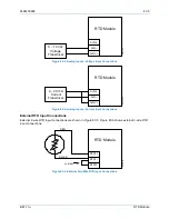
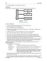
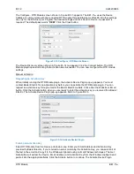
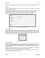
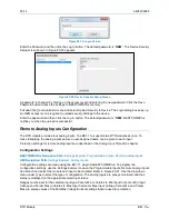
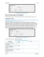
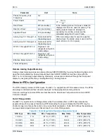
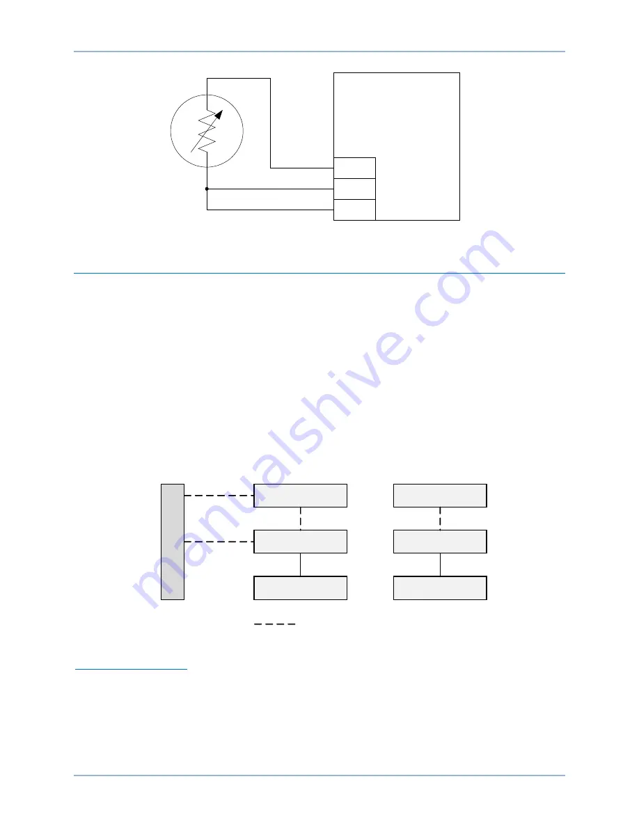
Figure 83-6. External Three-Wire RTD Input Connections
RTD Module Communications Setup Procedure
Communication between the BE1-11
m
and the RTD module can be accomplished via Ethernet or RS-
485. For RS-485 communication, RS-485 Port Protocol option must be “N”. Initial settings for the RTD
module must be made via Ethernet.
An IP address is assigned to the RTD module in all cases even if the connection between the RTD
module and the BE1-11
m
will be RS-485. Assigning an IP address to the RTD module gives the user the
option to save a settings file and to view the serial number and firmware version of the RTD module using
BESTCOMS
Plus
.
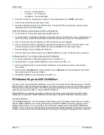
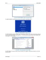
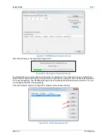
Perform one of the following procedures to set up the RTD module. It is assumed that the BE1-11
m
is
already connected to the PC or network.
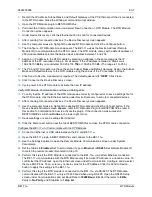
Procedure 1
The PC and BE1-11
m
are connected through a network or the PC is connected directly to the BE1-11
m
via Ethernet cable or USB cable. The RTD module connects to the BE1-11
m
via Ethernet or RS-485. See
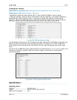
Figure 83-7. Procedure 1
Connect to RTD Module
1.
Connect an Ethernet cable directly between the PC and RTD module.
2.
Apply operating power to the RTD module.
3.
Determine the IP address, Subnet Mask, and Default Gateway of the PC Ethernet port for later use.
Open a Windows
®
command prompt by clicking Start > Run
.
Type “cmd”, and click OK. Type
“ipconfig” and press enter.
RTD1+
RTD1–
RTD1C
RTD Module
P0
06
1-
41
RED
BLACK
BLACK
N
e
t
w
o
r
k
PC
BE1-11
m
RTD Module
Ethernet
Ethernet
P0
06
1-
85
RS-485
Ethernet
= Optional
OR
PC
BE1-11
m
RTD Module
Ethernet
USB
Содержание BE1-11m
Страница 8: ...vi 9424200996 Revision History BE1 11m...
Страница 12: ...x 9424200996 Contents BE1 11m...
Страница 21: ...9424200996 1 9 BE1 11m Introduction Figure 1 1 Style Chart...
Страница 22: ...1 10 9424200996 Introduction BE1 11m...
Страница 40: ...3 6 9424200996 Controls and Indicators BE1 11m Figure 3 3 Front Panel Display Setup Screen...
Страница 53: ...9424200996 5 5 BE1 11m Phase Undervoltage 27P Protection Figure 5 3 Phase Undervoltage Settings Screen...
Страница 54: ...5 6 9424200996 Phase Undervoltage 27P Protection BE1 11m...
Страница 56: ...6 2 9424200996 Negative Sequence Voltage 47 Protection BE1 11m...
Страница 61: ...9424200996 7 5 BE1 11m Phase Overvoltage 59P Protection Figure 7 3 Overvoltage Settings Screen...
Страница 62: ...7 6 9424200996 Phase Overvoltage 59P Protection BE1 11m...
Страница 68: ...8 6 9424200996 Auxiliary Overvoltage 59X Protection BE1 11m...
Страница 80: ...12 4 9424200996 Instantaneous Overcurrent 50 Protection BE1 11m...
Страница 84: ...13 4 9424200996 Breaker Failure 50BF Protection BE1 11m...
Страница 91: ...9424200996 14 7 BE1 11m Inverse Overcurrent 51 Protection Figure 14 4 Inverse Overcurrent Settings Screen...
Страница 92: ...14 8 9424200996 Inverse Overcurrent 51 Protection BE1 11m...
Страница 105: ...9424200996 18 3 BE1 11m Power Factor 55 Protection Figure 18 2 Power Factor Settings Screen...
Страница 106: ...18 4 9424200996 Power Factor 55 Protection BE1 11m...
Страница 110: ...19 4 9424200996 Resistance Temperature Detector 49RTD Protection BE1 11m...
Страница 118: ...20 8 9424200996 Thermal Curve 49TC Protection BE1 11m...
Страница 122: ...22 2 9424200996 Starts per Time Interval 66 Protection BE1 11m...
Страница 124: ...23 2 9424200996 Restart Inhibit Protection BE1 11m...
Страница 130: ...25 4 9424200996 Virtual Control Switches 43 BE1 11m Figure 25 3 Virtual Control Switches Settings Screen...
Страница 140: ...28 4 9424200996 Breaker Control Switch 101 BE1 11m...
Страница 148: ...29 8 9424200996 Setting Groups BE1 11m...
Страница 156: ...30 8 9424200996 Metering BE1 11m Figure 30 11 RTD Meter Screen...
Страница 158: ...31 2 9424200996 Digital Points BE1 11m Figure 31 2 Digital Points Monitor Screen...
Страница 177: ...9424200996 34 5 BE1 11m Motor Reporting Figure 34 9 Learned Motor Data Screen...
Страница 178: ...34 6 9424200996 Motor Reporting BE1 11m...
Страница 184: ...35 6 9424200996 Alarms BE1 11m...
Страница 186: ...36 2 9424200996 Differential Reporting BE1 11m...
Страница 196: ...38 4 9424200996 Demands BE1 11m...
Страница 198: ...39 2 9424200996 Load Profile BE1 11m...
Страница 207: ...9424200996 41 5 BE1 11m Trip Circuit Monitor 52TCM Figure 41 6 Trip Circuit Monitor Settings Screen...
Страница 208: ...41 6 9424200996 Trip Circuit Monitor 52TCM BE1 11m...
Страница 212: ...42 4 9424200996 Fuse Loss 60FL BE1 11m...
Страница 218: ...43 6 9424200996 BESTnet Plus BE1 11m Figure 43 8 Power Quality Page...
Страница 221: ...9424200996 44 3 BE1 11m Mounting Figure 44 3 Case Side Dimensions...
Страница 227: ...9424200996 44 9 BE1 11m Mounting Figure 44 9 Retrofit Mounting Plate Basler P N 9424200073 Part 2...
Страница 235: ...9424200996 45 5 BE1 11m Terminals and Connectors Figure 45 7 Example of Reversed CT Polarity...
Страница 236: ...45 6 9424200996 Terminals and Connectors BE1 11m...
Страница 269: ...9424200996 48 15 BE1 11m BESTlogic Plus Figure 48 4 Logic Page 1 for Default Logic...
Страница 288: ...49 10 9424200996 Communication BE1 11m Figure 49 14 Modbus Mapping Screen...
Страница 301: ...9424200996 51 5 BE1 11m Timekeeping Figure 51 3 Front Panel Circuit Board Backup Battery Location...
Страница 306: ...52 4 9424200996 Device Information BE1 11m...
Страница 314: ...53 8 9424200996 Configuration BE1 11m Figure 53 3 Display Units Screen...
Страница 318: ...54 4 9424200996 Introduction to Testing BE1 11m...
Страница 330: ...56 6 9424200996 Commissioning Testing BE1 11m...
Страница 336: ...58 4 9424200996 Phase Undervoltage 27P Test BE1 11m...
Страница 340: ...59 4 9424200996 Phase Overvoltage 59P Test BE1 11m...
Страница 352: ...60 12 9424200996 Auxiliary Overvoltage 59X Test BE1 11m...
Страница 360: ...61 8 9424200996 Frequency 81 Test BE1 11m...
Страница 364: ...62 4 9424200996 Instantaneous Undercurrent 37 Test BE1 11m...
Страница 376: ...63 12 9424200996 Instantaneous Overcurrent 50 Test BE1 11m...
Страница 396: ...65 16 9424200996 Inverse Overcurrent 51 Test BE1 11m...
Страница 408: ...67 6 9424200996 Power 32 Test BE1 11m...
Страница 412: ...68 4 9424200996 Loss of Excitation Reverse Var Based 40Q Test BE1 11m...
Страница 426: ...70 10 9424200996 Thermal Curve 49TC Test BE1 11m...
Страница 432: ...72 4 9424200996 Starts per Time Interval 66 Test BE1 11m...
Страница 436: ...73 4 9424200996 Restart Inhibit Test BE1 11m...
Страница 440: ...74 4 9424200996 Virtual Control Switches 43 Test BE1 11m...
Страница 450: ...75 10 9424200996 Logic Timers 62 Test BE1 11m...
Страница 464: ...79 8 9424200996 Troubleshooting BE1 11m...
Страница 480: ...80 16 9424200996 Specifications BE1 11m...
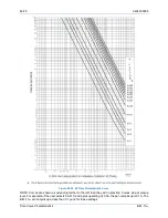
Страница 496: ...82 8 9424200996 Time Curve Characteristics BE1 11m Figure 82 3 Time Characteristic Curve A Standard Inverse BS 142...
Страница 497: ...9424200996 82 9 BE1 11m Time Curve Characteristics Figure 82 4 Time Characteristic Curve A1 Inverse IEC 60255 151 Ed 1...
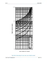
Страница 504: ...82 16 9424200996 Time Curve Characteristics BE1 11m Figure 82 11 Time Characteristic Curve G Long Time Inverse BS 142...
Страница 507: ...9424200996 82 19 BE1 11m Time Curve Characteristics Figure 82 14 Time Characteristic Curve B Very Inverse BS 142...
Страница 512: ...82 24 9424200996 Time Curve Characteristics BE1 11m Figure 82 19 Time Characteristic Curve C Extremely Inverse BS 142...
Страница 570: ...84 26 9424200996 Settings Calculation Examples BE1 11m Figure 84 31 Time vs Current and Thermal Limit Curves...
Страница 597: ...9424200996 84 53 BE1 11m Settings Calculation Examples Figure 84 67 Logic Page 1 Unchanged from Induction Motor Default...
Страница 598: ...84 54 9424200996 Settings Calculation Examples BE1 11m Figure 84 68 Logic Page 2 Unbalance Trip and Alarm Added...
Страница 599: ...9424200996 84 55 BE1 11m Settings Calculation Examples Figure 84 69 Logic Page 3 Power Factor 55 Added...
Страница 600: ...84 56 9424200996 Settings Calculation Examples BE1 11m Figure 84 70 Logic Page 4 Part 1...
Страница 602: ...84 58 9424200996 Settings Calculation Examples BE1 11m...
Страница 608: ...85 6 9424200996 BESTCOMSPlus Settings Loader Tool BE1 11m...
Страница 609: ......

