


9424200996
13-1
BE1-11
m
Breaker Failure (50BF) Protection
13 • Breaker Failure (50BF) Protection
The breaker failure (50BF) element provides protection and security for the power system against the
monitored breaker failing to open.
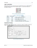
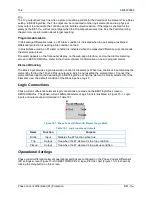
Element logic connections are made on the BESTlogic
™
Plus
screen in BESTCOMS
Plus
®
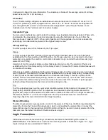
and element
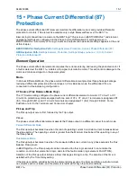
operational settings are configured on the Breaker Fail (50BF) settings screen in BESTCOMS
Plus
. A
summary of the logic inputs and outputs and operational settings appears at the end of this chapter.
BESTCOMS
Plus
Navigation Path:
Settings Explorer, Protection, Current, Breaker Fail (50BF)
HMI Navigation Path:
Settings Explorer, Protection, Settings Group x (where x = 0 to 3), Current
Protection, Breaker Fail 50BF
Element Operation
The 50BF element uses two methods to determine when the breaker has failed to open. The first method
uses the breaker status (52a or 52b input) to determine if the breaker has successfully opened. The
second method uses the monitored current to detect if the breaker has successfully opened.
In the first method, the breaker is closed when the Breaker Status (BRKSTAT) logic element is true. The
52BFI logic input is used to signal the breaker to open. When the BRKSTAT logic element and the 52BFI
logic input are true, a delay timer is initiated to allow time for the breaker to transition. If the time delay
expires and the BRKSTAT logic element and the 52BFI logic input are still true, the Trip output becomes
true, signaling that the breaker has failed to trip.
In the second method, monitored current is used to determine if the breaker is closed. The 50BFI logic
input of the Breaker Failure logic block is used to signal the breaker to open. When current is present and
the 50BFI logic input is true, a timer is initiated to allow time for the fault to clear. If the time delay expires
and current is still present, the Trip output becomes true, signaling that the breaker has failed to open. A
control timer specifies the duration the breaker can remain closed before a Breaker Fail alarm will occur.
In both methods above, a Breaker Fail Retrip (BFRT) will be true while the delay timer is true. A breaker
fail trip indicates a failed breaker. The Trip signal can be used to trip the next set of breakers upstream in
the power system. Breaker failure protection may be applied to any portion of the power system where
failure of a circuit breaker to operate properly could result in severe system damage or instability.
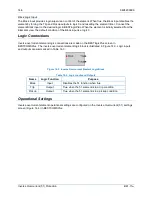
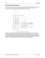
Contact Sensing
Before any relay output can occur, there must first be an initiating signal to the Breaker Failure logic
element. There are two possible initiating signals. The 52 Breaker Fail Initiate (52BFI) signal is the
initiation signal when breaker status is used to determine a breaker failure. The 50 Breaker Fail Initiate
(50BFI) is the initiation signal when current is used to determine a breaker failure. These initiate inputs
can be driven by other relays through BE1-11
m
contact inputs or GOOSE over IEC 61850. Alternately,
they can come from trip signals from other protective elements within the BE1-11
m.
Breaker status input
is provided by the BRKSTAT logic element.
Information on setting up the breaker status logic can be found in the
Breaker Monitoring
chapter.
Control Timer
The control timer provides a window of opportunity for a breaker failure Trip output to remain closed when
the 50BFI logic input is used to signal the breaker to open. It improves dependability by sealing in the
initiate request to prevent stopping of a breaker failure timing if the tripping relay drops out prematurely.
The control timer is initiated by a 50BFI signal. Upon sensing the 50BFI transition from a 0 to 1 state, the
control timer seals in the 50BFI signal for the duration of the Control Timer setting. If the control timer
expires and the 50BFI signal is still present, an alarm signal occurs. A control timer setting of zero (0)
disables the control timer seal-in function allowing the control timer to follow the 50BFI input.
Содержание BE1-11m
Страница 8: ...vi 9424200996 Revision History BE1 11m...
Страница 12: ...x 9424200996 Contents BE1 11m...
Страница 21: ...9424200996 1 9 BE1 11m Introduction Figure 1 1 Style Chart...
Страница 22: ...1 10 9424200996 Introduction BE1 11m...
Страница 40: ...3 6 9424200996 Controls and Indicators BE1 11m Figure 3 3 Front Panel Display Setup Screen...
Страница 53: ...9424200996 5 5 BE1 11m Phase Undervoltage 27P Protection Figure 5 3 Phase Undervoltage Settings Screen...
Страница 54: ...5 6 9424200996 Phase Undervoltage 27P Protection BE1 11m...
Страница 56: ...6 2 9424200996 Negative Sequence Voltage 47 Protection BE1 11m...
Страница 61: ...9424200996 7 5 BE1 11m Phase Overvoltage 59P Protection Figure 7 3 Overvoltage Settings Screen...
Страница 62: ...7 6 9424200996 Phase Overvoltage 59P Protection BE1 11m...
Страница 68: ...8 6 9424200996 Auxiliary Overvoltage 59X Protection BE1 11m...
Страница 80: ...12 4 9424200996 Instantaneous Overcurrent 50 Protection BE1 11m...
Страница 84: ...13 4 9424200996 Breaker Failure 50BF Protection BE1 11m...
Страница 91: ...9424200996 14 7 BE1 11m Inverse Overcurrent 51 Protection Figure 14 4 Inverse Overcurrent Settings Screen...
Страница 92: ...14 8 9424200996 Inverse Overcurrent 51 Protection BE1 11m...
Страница 105: ...9424200996 18 3 BE1 11m Power Factor 55 Protection Figure 18 2 Power Factor Settings Screen...
Страница 106: ...18 4 9424200996 Power Factor 55 Protection BE1 11m...
Страница 110: ...19 4 9424200996 Resistance Temperature Detector 49RTD Protection BE1 11m...
Страница 118: ...20 8 9424200996 Thermal Curve 49TC Protection BE1 11m...
Страница 122: ...22 2 9424200996 Starts per Time Interval 66 Protection BE1 11m...
Страница 124: ...23 2 9424200996 Restart Inhibit Protection BE1 11m...
Страница 130: ...25 4 9424200996 Virtual Control Switches 43 BE1 11m Figure 25 3 Virtual Control Switches Settings Screen...
Страница 140: ...28 4 9424200996 Breaker Control Switch 101 BE1 11m...
Страница 148: ...29 8 9424200996 Setting Groups BE1 11m...
Страница 156: ...30 8 9424200996 Metering BE1 11m Figure 30 11 RTD Meter Screen...
Страница 158: ...31 2 9424200996 Digital Points BE1 11m Figure 31 2 Digital Points Monitor Screen...
Страница 177: ...9424200996 34 5 BE1 11m Motor Reporting Figure 34 9 Learned Motor Data Screen...
Страница 178: ...34 6 9424200996 Motor Reporting BE1 11m...
Страница 184: ...35 6 9424200996 Alarms BE1 11m...
Страница 186: ...36 2 9424200996 Differential Reporting BE1 11m...
Страница 196: ...38 4 9424200996 Demands BE1 11m...
Страница 198: ...39 2 9424200996 Load Profile BE1 11m...
Страница 207: ...9424200996 41 5 BE1 11m Trip Circuit Monitor 52TCM Figure 41 6 Trip Circuit Monitor Settings Screen...
Страница 208: ...41 6 9424200996 Trip Circuit Monitor 52TCM BE1 11m...
Страница 212: ...42 4 9424200996 Fuse Loss 60FL BE1 11m...
Страница 218: ...43 6 9424200996 BESTnet Plus BE1 11m Figure 43 8 Power Quality Page...
Страница 221: ...9424200996 44 3 BE1 11m Mounting Figure 44 3 Case Side Dimensions...
Страница 227: ...9424200996 44 9 BE1 11m Mounting Figure 44 9 Retrofit Mounting Plate Basler P N 9424200073 Part 2...
Страница 235: ...9424200996 45 5 BE1 11m Terminals and Connectors Figure 45 7 Example of Reversed CT Polarity...
Страница 236: ...45 6 9424200996 Terminals and Connectors BE1 11m...
Страница 269: ...9424200996 48 15 BE1 11m BESTlogic Plus Figure 48 4 Logic Page 1 for Default Logic...
Страница 288: ...49 10 9424200996 Communication BE1 11m Figure 49 14 Modbus Mapping Screen...
Страница 301: ...9424200996 51 5 BE1 11m Timekeeping Figure 51 3 Front Panel Circuit Board Backup Battery Location...
Страница 306: ...52 4 9424200996 Device Information BE1 11m...
Страница 314: ...53 8 9424200996 Configuration BE1 11m Figure 53 3 Display Units Screen...
Страница 318: ...54 4 9424200996 Introduction to Testing BE1 11m...
Страница 330: ...56 6 9424200996 Commissioning Testing BE1 11m...
Страница 336: ...58 4 9424200996 Phase Undervoltage 27P Test BE1 11m...
Страница 340: ...59 4 9424200996 Phase Overvoltage 59P Test BE1 11m...
Страница 352: ...60 12 9424200996 Auxiliary Overvoltage 59X Test BE1 11m...
Страница 360: ...61 8 9424200996 Frequency 81 Test BE1 11m...
Страница 364: ...62 4 9424200996 Instantaneous Undercurrent 37 Test BE1 11m...
Страница 376: ...63 12 9424200996 Instantaneous Overcurrent 50 Test BE1 11m...
Страница 396: ...65 16 9424200996 Inverse Overcurrent 51 Test BE1 11m...
Страница 408: ...67 6 9424200996 Power 32 Test BE1 11m...
Страница 412: ...68 4 9424200996 Loss of Excitation Reverse Var Based 40Q Test BE1 11m...
Страница 426: ...70 10 9424200996 Thermal Curve 49TC Test BE1 11m...
Страница 432: ...72 4 9424200996 Starts per Time Interval 66 Test BE1 11m...
Страница 436: ...73 4 9424200996 Restart Inhibit Test BE1 11m...
Страница 440: ...74 4 9424200996 Virtual Control Switches 43 Test BE1 11m...
Страница 450: ...75 10 9424200996 Logic Timers 62 Test BE1 11m...
Страница 464: ...79 8 9424200996 Troubleshooting BE1 11m...
Страница 480: ...80 16 9424200996 Specifications BE1 11m...
Страница 496: ...82 8 9424200996 Time Curve Characteristics BE1 11m Figure 82 3 Time Characteristic Curve A Standard Inverse BS 142...
Страница 497: ...9424200996 82 9 BE1 11m Time Curve Characteristics Figure 82 4 Time Characteristic Curve A1 Inverse IEC 60255 151 Ed 1...
Страница 504: ...82 16 9424200996 Time Curve Characteristics BE1 11m Figure 82 11 Time Characteristic Curve G Long Time Inverse BS 142...
Страница 507: ...9424200996 82 19 BE1 11m Time Curve Characteristics Figure 82 14 Time Characteristic Curve B Very Inverse BS 142...
Страница 512: ...82 24 9424200996 Time Curve Characteristics BE1 11m Figure 82 19 Time Characteristic Curve C Extremely Inverse BS 142...
Страница 570: ...84 26 9424200996 Settings Calculation Examples BE1 11m Figure 84 31 Time vs Current and Thermal Limit Curves...
Страница 597: ...9424200996 84 53 BE1 11m Settings Calculation Examples Figure 84 67 Logic Page 1 Unchanged from Induction Motor Default...
Страница 598: ...84 54 9424200996 Settings Calculation Examples BE1 11m Figure 84 68 Logic Page 2 Unbalance Trip and Alarm Added...
Страница 599: ...9424200996 84 55 BE1 11m Settings Calculation Examples Figure 84 69 Logic Page 3 Power Factor 55 Added...
Страница 600: ...84 56 9424200996 Settings Calculation Examples BE1 11m Figure 84 70 Logic Page 4 Part 1...
Страница 602: ...84 58 9424200996 Settings Calculation Examples BE1 11m...
Страница 608: ...85 6 9424200996 BESTCOMSPlus Settings Loader Tool BE1 11m...
Страница 609: ......