Baroness TDA1200 Скачать руководство пользователя страница 43

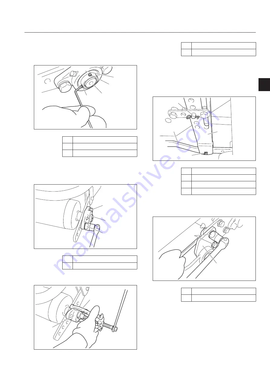
Loosen the hollow set securing the roller
shaft of the flange unit.
Follow the same steps to loosen the one on
the opposite side.

1

2

2

3

oxwlid-003

Removal of rear roller Assy_003

1

Flange unit

2

Hollow set

3

Roller shaft

Remove the bolts and spring washers of
the flange unit.
Follow the same steps to remove those on
the other side.

1

2

2

oxwlid-004

Removal of rear roller Assy_004

1

Flange unit

2

Bolt and spring washer

Remove the flange unit by using a pulley
puller.

1

2

oxwlid-005

Removal of rear roller Assy_005

3.

4.

5.

1

Pulley puller

2

Flange unit

Remove snap pin A and the flat-head pin
securing the rear roller bracket (R).
Remove snap pin B and the flat-head pin
securing the roller mounting strap, lift the
strap to the top, and then secure it with
snap pin B and the flat-head pin.

1

2

3

4

oxwlid-006

Removal of rear roller Assy_006

1

Snap pin A and flat-head pin

2

Snap pin B and flat-head pin

3

Rear roller bracket (R)

4

Roller hanging strap

Remove the bolt, washer, and U nut from
the front roller bracket and then the bracket
mounting board.

2

1

oxwlid-007

Removal of rear roller Assy_007

1

Bolt, washer, and U nut

2

Bracket mounting board

6.

7.

8.

Operating Machine and Mower Units

TDA1200

TDA1600

Operating Machine and Mower Units

Page 4-21

Removal and installation of each section

Содержание TDA1200

Страница 1: ...Tractor Mounted Aerator Service Manual Serial No TDA1200 20004 TDA1600 20004 Ver 1 1...

Страница 2: ...aroness parts or parts designated by Kyoeisha Note that the Baroness product warranty may not apply to defects caused by the use of parts from other companies Warning Symbols This manual uses the foll...

Страница 3: ...3 2 Tightening torques Page 3 4 Lifting Page 3 7 Greasing Page 3 8 Operating Machine and Mower Units Page 4 1 Maintenance Page 4 2 Specifications Page 4 2 Special Tool Page 4 4 Removal and installati...

Страница 4: ...TDA1200 TDA1600 Contents...

Страница 5: ...e 1 2 Training Page 1 2 Preparation Page 1 2 Driving Page 1 3 Maintenance and storage Page 1 4 Safety Signs and Instruction Signs Page 1 5 About Safety Signs and Instruction Signs Page 1 5 Safety TDA1...

Страница 6: ...e for its task 1 2 3 1 2 Lack of awareness of the effect of ground conditions especially slopes Incorrect hitching and load distribution Never allow children or people unfamiliar with these instructio...

Страница 7: ...e or wheel balance 5 5 6 7 1 2 3 4 5 1 2 3 4 5 6 7 Never operate the machine with guards shields damaged or without safety protective devices in place Be sure not to remove the interlock system Make n...

Страница 8: ...ipment with fuel in the tank inside a building where fumes may reach an open flame or spark 17 18 19 20 21 22 23 1 2 3 4 5 If the engine is provided with a shut off valve shut off valve while storing...

Страница 9: ...labels Check that all nuts bolts and screws are properly tightened to ensure that the machine is always operated under safe working conditions When the fuel tank needs to be cleaned do it outdoors Sa...

Страница 10: ...TDA1200 TDA1600 Safety Page 1 6 Safety Signs and Instruction Signs...

Страница 11: ...Waste Disposal Page 2 2 About the Waste disposal Page 2 2 Disposal TDA1200 TDA1600 Disposal Page 2 1...

Страница 12: ...l Make sure that waste generated when servicing or repairing the machine is disposed of in accordance with local regulations e g waste oil antifreeze batteries rubber products and wires etc TDA1200 TD...

Страница 13: ...3 4 Standard tightening torques Page 3 4 Principal tightening torques Page 3 5 Lifting Page 3 7 Lifting point Page 3 7 Lifting point and jack stand point Page 3 7 Greasing Page 3 8 About Greasing Pag...

Страница 14: ...2 0 21875 5 556 23 32 0 71875 18 256 15 64 0 234375 5 953 47 64 0 734375 18 653 1 4 0 2500 6 350 3 4 0 7500 19 050 17 64 0 265625 6 747 49 64 0 765625 19 447 9 32 0 28125 7 144 25 32 0 78125 19 844 19...

Страница 15: ...eters Cubic Centimeters m3 m3 cm3 0 7646 0 02832 16 39 Weight Tons Short Pounds Ounces Avdp sh tn lb oz Metric Tons Kilograms Grams ton kg g 0 9078 0 4536 28 3495 Pressure Pounds Sq In Pounds Sq In ps...

Страница 16: ...friction therefore sufficient tightening cannot be applied If screw is wet by water or oil do not tighten it with normal tightening torque If the screw is wet the torque coefficient will get smaller...

Страница 17: ...4 670 6 831 99 5 930 17 M27 1 000 10 197 00 8 851 00 M30 1 340 14 628 78 11 860 34 Note The same values are applied to fine screw thread Principal tightening torques Tightening Torque by Model TDA1200...

Страница 18: ...010120502 Bolt heat treated M12 50 104 134 1060 8 1366 8 920 71 1186 31 K0010100602 Bolt heat treated M10 60 58 76 591 6 775 2 513 47 672 82 K0024100251 Bolt w hexagon hole M10 25 29 38 295 8 387 6 25...

Страница 19: ...other positions than the specified ones Doing so the frames and parts may get damaged Lifting point and jack stand point Lifting point Front frame and rear frame Caution Attach the slings to the fron...

Страница 20: ...es are installed in the following locations Add grease every 50 hours of operation 1 2 2 3 5 6 4 6 4 8bq62b 213 Greasing points_001 Location No of Greasing Points 1 Rear roller 2 2 Front roller 2 3 Cl...

Страница 21: ...cross 8bq62b 217 Greasing points_005 Safety cover Use lithium grease urea type with molybdenum One location in each safety covers 8bq62b 218 Greasing points_006 3 4 5 Slide inner outer tubes Pull out...

Страница 22: ...TDA1200 TDA1600 Maintenance standards and maintenance Page 3 10 Greasing...

Страница 23: ...4 6 Lower housing Assy Page 4 7 Spring box Page 4 9 Crank Assy Page 4 10 Gearbox Page 4 15 Front Roller Assy Page 4 19 Rear Roller Assy Page 4 20 Front roller bracket Page 4 22 Inspection and repair o...

Страница 24: ...0 1600 Owner s Operating Manual and Parts Catalog For information on attaching and removing optional parts and attachments please refer to the handling manual for the corresponding attachment Specific...

Страница 25: ...ting machine and mower units Grease Excelite EP No 2 urea type Use the following type of grease on the drive shaft Grease Lithium grease urea type with molybdenum Oil Use the following type of oil on...

Страница 26: ...ings with outer 85 and inner 45 6204 Bearing driver q9c6v6 009 K4802000762 Used when installing bearings with outer 47 and inner 20 6208 Bearing driver q9c6v6 009 K4802000772 Used when installing bear...

Страница 27: ...in and install the bearing of outer 52 and inner 25 6206 Bearing driver q9c6v6 009 K4802000832 Used when installing bearings with outer 62 and inner 30 Operating Machine and Mower Units TDA1200 TDA160...

Страница 28: ...mounting board Turn the crank and place the tine holder on a stage so that the 12 18 tine mounting board can be removed from that tine holder 1 2 1 Install the socket on the spinner handle and remove...

Страница 29: ...Warning When removing or installing any crank parts be sure to secure the crank If the crank is not secured the crank may become unbalanced and rotate suddenly It may cause injury or death The machin...

Страница 30: ...il locking is released Loosen the nuts of the bolts which are connecting the crank housing with the lower housing Assy 1 2 3 mgo9ef 004 Removal of lower housing Assy_004 1 Crank housing 2 Bolt washer...

Страница 31: ...may not apply to any defects caused by incorrect or overtorque tightening etc For installation reverse the removing procedure Spring box Removal of spring box Warning When removing or installing any c...

Страница 32: ...that attach the sling to the crank housing at the highest point after setting the spring box to be removed at the lowest point and follow the same procedure Installation of spring box Caution Refer t...

Страница 33: ...val of crank Assy_001 1 Slotted nut 2 Cotter pin Caution When removing and installing the crank nuts be sure to secure the crank Secure the crank bracket by using a wood block etc so that it does not...

Страница 34: ...ing 2 Crank Assy 10 11 12 13 Remove the other crank Assy in the same procedure Installation of crank Assy Warning When removing or installing any crank parts be sure to secure the crank If the crank i...

Страница 35: ...g bracket 1 2 2 ntasjc 003 Installation of crank Assy_003 1 Main body housing bracket 2 Crank housing 2 3 Install housing mounting bracket A with bolts spring washers and washers at two points 3 1 2 2...

Страница 36: ...racket 2 Left crank Assy side crank bracket A 3 Crank shaft Install the disc spring and slotted nut on the crank shaft Secure the crank bracket with a wood block etc in the rotation direction to tight...

Страница 37: ...001 1 2 1 Gearbox 2 Upper arm 3 Slotted nut and cotter pin Caution When removing and installing the crank nuts be sure to secure the crank Secure the crank bracket by using a wood block etc so that it...

Страница 38: ...rank bracket 5 Bolt nut and spring washer 8 9 10 Remove the crank brackets from the drive shaft by using a pulley puller Remove the one in the opposite side as well in the same procedure 1 2 usrzwg 00...

Страница 39: ...carefully from the main body 1 usrzwg 009 Removal of gear box_009 1 Gearbox Installation of gear box Warning When removing or installing any crank parts be sure to secure the crank If the crank is not...

Страница 40: ...washers and washers on the specific torque 1 2 3 2 3 c8hvyh 004 Installation of gear box_004 1 Housing mounting board 2 Bolt and spring washer 3 Washer Tighten the temporarily tightened bolts on the u...

Страница 41: ...r 3 Wood block Tighten the slotted nuts of the drive shaft and crank shaft on the specified torque See Gear box layout Page 4 15 Install the slotted pins 11 12 13 14 15 Front Roller Assy Removal of fr...

Страница 42: ...es Page 3 4 Note that the Baroness product warranty may not apply to any defects caused by incorrect or overtorque tightening etc For installation reverse the removing procedure Rear Roller Assy Remov...

Страница 43: ...lange unit Remove snap pin A and the flat head pin securing the rear roller bracket R Remove snap pin B and the flat head pin securing the roller mounting strap lift the strap to the top and then secu...

Страница 44: ...val of front roller bracket_001 1 Rear frame 2 Sling 3 Rear roller 9 1 Remove snap pin A and the flat head pin securing the rear roller Assy Follow the same steps to remove those on the other side 1 2...

Страница 45: ...the same steps to remove those on the other side 1 2 3 5 6 4 kqszfp 003 Removal of front roller bracket_005 1 Sling 2 Bolt and spring washer 3 Front roller Assy 4 Flange unit 5 Grass pressing mountin...

Страница 46: ...roller stopper and fastening plate together while holding the front roller bracket 1 kqszfp 008 Removal of front roller bracket_010 1 Front roller bracket Installation of front roller bracket Caution...

Страница 47: ...there is no bent crack or break on the lower arm Make sure that there is no bent or wear on the arm axis Remove the bolts washers and U nut A from the lower housing Assy and then remove the upper arm...

Страница 48: ...ith a bearing and the lower housing B with a bearing too 1 2 lyl9n4 006 TDA1200_006 1 Tine holder with a bearing 2 Vise Caution Tightening torques Page 3 4 See the list Note that the Baroness product...

Страница 49: ...a driver tool 1 2 lyl9n4 009 TDA1200_009 1 Tine holder 2 Driver 12 13 Insert the colors into the lower housing A lower housing B and tine holder 1 lyl9n4 010 TDA1200_010 1 Collar Drive the bearings i...

Страница 50: ...200_015 1 Bolt washer and U nut 2 Upper arm 3 Lower housing A TDA1600 Wear of bearings due to frequent usage and invasion of water may damage bearings etc preventing smooth rotation of the tine holder...

Страница 51: ...he bearing collar 1 1 iiprkx 003 TDA1600_003 1 Bearing collar 2 3 4 Strike the arm axis by using a wood hummer to remove it and then remove the lower housing B collar bearing and bearing collar 2 1 4...

Страница 52: ...axis and then remove the tine holder from the bolt 7 8 9 Remove the bolt from the time holder A 1 5 4 3 2 iiprkx 008 TDA1600_008 1 Arm axis 2 Collar 3 Tine holder 4 Bolt 5 Tine holder A Hang the click...

Страница 53: ...he lock plate on the arm axis Important Install the bearing collars with taking care of their correct directions 13 14 15 Insert bearing collars in each arm axis UP 4 1 3 2 iiprkx 012 TDA1600_012 1 Lo...

Страница 54: ...nd then drive its bearing by using a driver tool 2 1 iiprkx 017 TDA1600_017 19 20 21 1 Collar 2 Bearing Drive the lower housing A by using a driver tool and then insert its collar 1 2 iiprkx 018 TDA16...

Страница 55: ...ower arm 1 iiprkx 023 TDA1600_023 1 Lower arm Install the washers and U nuts onto 2 arm axes of the lower arm Install the washer and U nut onto the bolt A which holds the tine holder Important There a...

Страница 56: ...spring is not broken nor shrunk Note Between the spring box Assys of TDA1200 and TDA1600 the spring box compression box and spring shaft varies but the assembling and inspection methods are the same R...

Страница 57: ...ng box_006 1 Fastening bracket Pull out the spring shaft Assy 1 pue9kj 007 Inspection of spring box_007 1 Spring shaft Assy 6 7 8 Remove the spiral pin from the spring stopper 2 1 pue9kj 008 Inspectio...

Страница 58: ...with a new one 2 3 1 pue9kj 012 Inspection of spring box_012 1 Spring box 2 Hollow set spring washer and nut 3 Urethane sheet Caution Tightening torques Page 3 4 See the list Note that the Baroness p...

Страница 59: ...pring shaft Assy into the spring box 2 1 pue9kj 014 Inspection of spring box_015 1 Spring shaft Assy 2 Spring box Tighten the fastening bracket and adjust it to the angle where the screw hole of the s...

Страница 60: ...e upper housing crank bracket and crank bracket A Make sure that there is no wear or damage of the drive shaft nor crank shaft Make sure that there is no wear or rust of the bearing Make sure that the...

Страница 61: ...5 6 Open the angle between the crank bracket and crank bracket A by using the crank shaft as a fulcrum so that the angle between them will become 180 Remove the crank housing Assy by using a pulley p...

Страница 62: ...Inspection of crank Assy_009 12 13 14 1 Upper housing 2 Bearing and collar Important Be sure to replace the bearings disc springs and cotter pins with new ones Important The drive shaft has a specifi...

Страница 63: ...zg3t 015 Inspection of crank Assy_015 1 Crank bracket Install and temporarily fasten the disc spring and cotter nut 1 ogzg3t 016 Inspection of crank Assy_016 1 Slotted nut and disc spring Fit and inse...

Страница 64: ...tighten them until the bolts hit the keys and lock them with nuts Install the other crank Assys in the same way Crank housing Crank housing layout 1 1 onpou8 001 Crank housing layout_001 1 Crank hous...

Страница 65: ...g_002 1 Vise 2 Drive shaft Place the drive shaft on the vise to provide a space for the shaft to come out 2 3 4 5 Remove the drive shaft by striking it with a wooden hummer to prevent any damage on th...

Страница 66: ...on drive shaft C Check there is no abnormality in both keys Check the wear on each stop ring Do not re use spring pin O ring oil seal and seal washer replace with new ones Important Always replace spr...

Страница 67: ...on spring B and steel ball Slide gearbox cover off of shifter fork to remove 1 2 3 5s6or7 034 Inspection of gear box_005 4 5 1 2 3 4 3 4 5 5s6or7 035 Inspection of gear box_006 1 Gearbox cover 2 Shift...

Страница 68: ...Remove stop ring from drive shaft B 1 2 5s6or7 038 Inspection of gear box_009 1 Drive shaft B 2 Stop ring 7 1 2 3 4 5 6 8 Remove oil seal from opposite side of gearbox 1 2 5s6or7 039 Inspection of ge...

Страница 69: ...ear box_015 1 Drive shaft A 12 13 1 2 14 Remove bearing from gearbox using drive shaft A Tap on drive shaft in the direction of the white arrow Remove drive shaft A from gearbox Remove bearing from dr...

Страница 70: ...e M20 TDA1600 use M24 3 Drive shaft C 4 Crankshaft housing Using a box cutter or long blade cut away at packing and sealant between crankshaft housing and crank gearbox A 3 1 2 5s6or7 050 Inspection o...

Страница 71: ...in the direction of arrow 2 1 5s6or7 054 Inspection of gear box_025 21 22 23 1 Crank gearbox B 2 Drive shaft B Remove oil seal from crank gearbox A Also remove oil seal from crankshaft housing not pic...

Страница 72: ...ers to threaded side of drive shaft C and fasten M20 nut This is to protect the threaded portion of drive shaft C To remove 30 tooth bevel gear from pipe place drive shaft C Assy in pipe making sure n...

Страница 73: ...n driving in the oil seal apply the liquid gasket equivalent to ThreeBond 1104 on the outer surface 1 2 5s6or7 016 Inspection of gear box_033 1 Oil seal 2 Liquid gasket ThreeBond 1104 29 30 In the hol...

Страница 74: ...4 5s6or7 064 Inspection of gear box_037 1 Drive shaft C Assy 2 Bearing 3 Driving tool 4 Vice 33 1 2 3 34 Flip drive shaft C Assy in the vice and balance on bearing Using driving tool to set other bear...

Страница 75: ...damage bevel gear part of drive shaft B Please note depth allowance of vice or base when hammering shaft into bearing Please tap drive shaft B into bearing with a plastic hammer 1 5s6or7 070 Inspecti...

Страница 76: ...Inspection of gear box_046 1 Drive shaft C Assy 2 Crank gearbox A 41 1 2 3 42 Carefully insert drive shaft C Assy into the oil seal of crank gearbox A Be careful not to tear or damage the oil seal Wi...

Страница 77: ...clear the groove notched out for the stop ring 1 5s6or7 077 Inspection of gear box_050 1 Driving tool 45 46 Important Flat side of stop ring should be facing away from bearing Install stop ring Make s...

Страница 78: ...49 1 2 50 1 2 Place bearing into crank gearbox A Use driving tool to set into position Install stop ring Make sure stop ring is positioned correctly and fully sitting in groove Flat side of stop ring...

Страница 79: ...ng 53 1 2 54 Install stop ring Make sure stop ring is positioned correctly and fully sitting in groove Flat side of stop ring should be facing away from bearing 1 5s6or7 086 Inspection of gear box_059...

Страница 80: ...gear box_064 58 1 2 3 4 59 1 2 shaft 14 tooth gear 2 Drive shaft B Install 2 washers onto drive shaft B Now install bearing onto drive shaft B 1 2 5s6or7 092 Inspection of gear box_065 1 Washers 2 Bea...

Страница 81: ...n bolt head and nut A 6 8 mm Once proper tension and adjustment is made lock into position by fastening lock nut 1 A 5s6or7 096 Inspection of gear box_069 1 Bolt pushing compression spring Align packi...

Страница 82: ...Washers 6 Bolt washers U nut 65 1 2 3 4 5 Rear roller bracket Assy Inspection of rear roller bracket Assy Wear of bearings due to frequent usage and invasion of water may damage bearings etc and prev...

Страница 83: ...he bearing 2 1 4es8d4 004 Inspection of rear roller bracket Assy_004 1 Stop ring 2 Bearing 2 3 4 Remove the bearing by using a driver 1 4es8d4 005 Inspection of rear roller bracket Assy_005 1 Driver I...

Страница 84: ...1 4es8d4 007 Inspection of rear roller bracket Assy_007 1 Bearing 2 Driver Drive in the bracket mounting board to the rear roller bracket and install the stop ring 2 1 4es8d4 008 Inspection of rear ro...

Страница 85: ...Specifications Page 5 2 Maintenance Schedule Page 5 3 List of Consumables Page 5 4 Reference TDA1200 TDA1600 Reference Page 5 1...

Страница 86: ...nits various types are available as options 24 units various types are available as options Operating depth Up to 25 cm 9 84 in depending on the conditions Up to 18 cm 7 09 in depending on the conditi...

Страница 87: ...rk After work Every 8 hrs Every 50 hrs Every 100 hrs Every 200 hrs Every 300 hrs Every 400 hrs Every 500 hrs Every 1 years Every 2 years Every 4 years Remarks Main body Tightening the parts Tine Opera...

Страница 88: ...A 3 For right grass keep plate TDA16000602ZD Grass keep plate for double type 8B 1 Standard tine K2590000220 17V tine 215 18 TDA1600 Code Part name Qty Remarks Operating machine mower unit Spring box...

Страница 89: ...Head Office 1 26 Miyuki cho Toyokawa Aichi Pref 442 8530 Japan Tel 0533 84 1390 Fax 0533 89 3623 TDA1200 SM GBZ 17B 00 S K...

Отзывы: