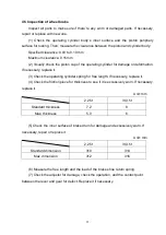
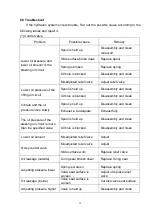
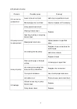


65
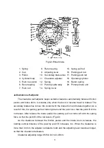
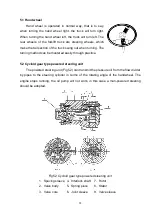
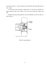
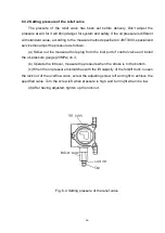
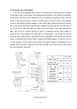
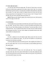
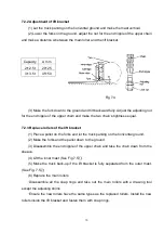
6.3.1 Relief valve and flow divider (see Fig6.3)
The relief valve consists of main valve A and proceeding valve B. When the spool of
the control valve is operated, chamber Q linked with the operating cylinder is filled with
high pressure oil. The high pressure oil affects proceeding valve B through throttle hole D
and E. If the system pressure is higher than the setting pressure, the proceeding valve B
will be opened to make the pressure in F chamber lower and thus causes the main valve
A to move right, then the oil in chamber Q may directly flow to low-pressure passage G
and reduce chamber Q pressure. In this way, the system pressure may keep unvaried.
The setting pressure may be adjusted by the adjusting screw H.
The construction of the flow divider is quite simple. It is of direct overflow type, and
ensures the constant pressure of the power steering system by balancing the oil pressure
with fixed spring force. When turning, chamber M gets through with the high pressure
passage. If the oil pressure is higher than the spring force, the valve core N moves right,
causing the high pressure oil to flow directly to the low-pressure passage via. Chamber T
and keeping the pressure of the power steering system unvaried. The setting pressure is
adjusted by adjusting the screw K.
Valve L is a balance spool valve, and may move right or left according to the variety
of the oil flow and pressure passing through it to change the opening of chamber R and S
and ensures the oil flow to working chamber Q and to power steering port PS keeps in
balance condition and is smoothly divided in certain proportion. Hole a is a fixed throttle
hole.
Fig6.3 Relief valve and flow divider
Содержание F Series
Страница 1: ...1...
Страница 7: ...1 About F series forklift truck 1 External view and technical parameter Fig1 1 External view...
Страница 95: ...89 Fig8 3 1 Diagram of harness 4JG2 engine...
Страница 96: ...90 Fig8 3 2 Diagram of harness Dachai 498 engine...
Страница 97: ...91 Fig8 3 3 Diagram of harness Xinchai 498engine...
Страница 98: ...92 Fig8 3 4 Diagram of harness Yanmar 4TNE98 engine...
Страница 99: ...93 NOTE...
Страница 100: ...94...
Страница 102: ......


