background image

Banner AG4 Series Safety Laser Scanner 


8


Maintenance and Repairs 

8.1


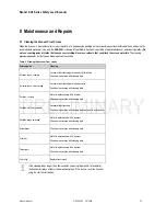
Cleaning the Scanner Front Screen 

Clean the Scanner’s front and scatter screens regularly, at a frequency depending on the surrounding environmental conditions, and using the 

recommended materials. (Use only the 

AG4-CLN..

 cleaning kit specified in Section 2, consisting of approved cleanser and cleaning cloths.) 

Do 

not use scouring pads or cloths that can cause scratching. Never use solvents that can attack the screen materials.

 The cleaning 

procedure depends on the type and degree of contamination. 

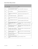
Table 8.  Cleaning the Scanner front  screen 

Contamination 

Cleaning 

Particles, loose, scouring 

Vacuum without touching or blow away softly, oil-free 

Wipe free in one swipe with cleaning cloth 

Particles, loose, non-scouring 

Vacuum without touching or blow away softly 

Wipe free in one swipe with cleaning cloth 

Particles, sticking 

Wet with cloth soaked in AG4 cleanser 

Wipe free in one swipe with cleaning cloth 

Particles, statically charged 

Vacuum without touching 

Wipe free in one swipe with cleaning cloth soaked with AG4 cleanser 

Particles/drops, smearing 

Wet with cloth soaked in AG4 cleanser 

Wipe free in one swipe with cleaning cloth 

Water drops 

Wipe free in one swipe with cleaning cloth 

Oil drops 

Wet with cloth soaked in AG4 cleanser 

Wipe free in one swipe with cleaning cloth 

Fingerprints 

Wet with cloth soaked in AG4 cleanser 

Wipe free in one swipe with cleaning cloth 

Scratches 

Replace front screen 


If the cleaning takes longer than four seconds (removing fingerprints, for example), 
the Scanner displays a front screen monitoring fault. If this occurs, reset the Scanner 

using the start/restart button. 

Product Manual  

P/N 144924      05/2009 

63 


Содержание AG4-4E

Страница 1: ...Banner AG4 Series Safety Laser Scanner Product Manual P N 144924 05 2009 1...

Страница 2: ...ided or the appropriateness of the provided information for a specific application The user has the responsibility to ensure that all local state and national laws rules codes and regulations relating...

Страница 3: ...ling the Scanner 12 1 11 Scanner Limitations 12 1 12 Providing the machine operator with information 13 1 13 Basic Operation Functions 13 1 14 Start restart reset interlock 13 1 14 1 Start interlock 1...

Страница 4: ...l Protective Field Applications US European Standards 36 4 5 8 C for Horizontal Protective Field Applications parallel approach 37 4 6 Application Examples 38 4 6 1 Danger zone parallel approach 38 4...

Страница 5: ...3 1 PF description 55 6 3 2 WF description 55 7 Safety System Testing 56 7 1 Prescribed Test Schedule 56 7 2 Initial Periodic Operation Check 56 7 3 Configuration Recommendations 57 7 4 Restart 57 7 5...

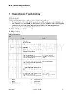
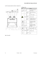
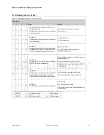
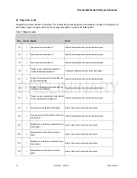
Страница 6: ...canner 9 2 LED status displays 67 9 3 LED warning and error displays 69 9 4 Diagnostics codes 70 EC Declaration of Conformity 76 10 Glossary 77 10 1 List of Abbreviations 77 10 2 List of terms 77 6 P...

Страница 7: ...afety outputs OFF Only when the PF is free of obstructions does the Scanner turn the safety outputs back ON either automatically or following a manual restart reset signal depending on the operating m...

Страница 8: ...hed on ON Start restart interlock is active Flashes 2 Hz Front screen is dirty 5 yellow Flashes 4 Hz Fault Figure 3 Status LEDs 1 2 Mounting System Optional The mounting system makes it easier to inst...

Страница 9: ...n plate The product identification plate is located on the top of the AG4 and details information as shown below Figure 4 Product identification plate 1 4 2 Safety Notice A Safety notice is located on...

Страница 10: ...arts against the dangers of collision The Scanner may only be used after it has been put into operation in accordance with the applicable instructions relevant rules and regulations on occupational he...

Страница 11: ...e machine operator supervisor is responsible for Instructing the operator Maintaining the safe operation of the machine Compliance with all occupational health and safety at work regulations and direc...

Страница 12: ...se on vehicles with combustion engines because alternators or ignition systems can cause EMC disturbances Make no modifications to the Scanner The construction of the Scanner may not be modified or th...

Страница 13: ...a rings guards key or other means If any areas are not visible from the reset switch additional means of safeguarding must be provided Failure to do so could result in serious bodily injury or death T...

Страница 14: ...e AG4 Scanner is configured for Automatic Start Restart operation the sensor will turn its safety outputs on as soon as the protective field is clear If the application requires a manual start restart...

Страница 15: ...erformed in a way that does not put personnel at risk Follow the guidelines listed here when changing the active Field Pair Use one or more diverse redundant sensors or switches to initiate a Field Pa...

Страница 16: ...3 0 0 1 0 Field pair 3 is active 4 0 0 0 1 Field pair 4 is active 5 1 1 1 0 Field pair 5 is active 6 1 1 0 1 Field pair 6 is active 7 1 0 1 1 Field pair 7 is active 8 0 1 1 1 All fields are deactivat...

Страница 17: ...9 RS232 cordset AG4 to PC PC connection cordset X2 10 m Accessories AG4 CLN1 82155 3082155 150 ml fluid 25 cloths AG4 CLN2 82156 3082156 AG4 cleaning kit includes approved fluid for cleaning plastic s...

Страница 18: ...nsing object reflectance Minimum 1 8 Warning Zone Min object size 150 mm x 150 mm Sensing range radius 200 mm to 15 m Sensing object reflectance Minimum 20 Measurement Zone 0 50 m Scanning Angle max 1...

Страница 19: ...rox in X Y and Z directions for twenty times each Max Cordset Length 15 pin plug 50 m 9 pin plug 10 m RS 232C 50 m RS 422 Design Standards Designed to comply with IEC 61496 1 3 Type 3 ISO 13849 1 Cate...

Страница 20: ...Banner AG4 Series Safety Laser Scanner 20 P N 144924 05 2009 Product Manual Mounting system option All dimensions in mm Figure 9 Mounting system dimensions...

Страница 21: ...st remain accessible The Scanner is applied as a stop activating and presence detecting protective device The Scanner s PF is set up horizontally in front of the machine hazard Danger zone guarding ca...

Страница 22: ...ive device The Scanner s PF is set up vertically in the front of the machine With small protective field dimensions range the Scanner provides the correspondingly required high resolution level A suff...

Страница 23: ...area Reset switches must also be out of reach from within the safeguarded space and must be protected against unauthorized or inadvertent operation via rings guards key or other means If any areas ar...

Страница 24: ...into the cell A side post and the floor serve as reference surfaces for monitoring the boundary of the PF In contrast to danger zone guarding the AG4 no longer detects a person in the cell after they...

Страница 25: ...cluding additional factors that can increase the minimum separation distances see the Minimum Separation Distance section further in the manual 5 Determine the start restart operating mode required fo...

Страница 26: ...truction Manual for more details This PF dimension requirement applies to both single field and multiple field switchover applications PFs with a range of less than 200 mm are not permitted this is a...

Страница 27: ...ccess this area undetected Failure to do so could result in serious bodily injury or death The area behind the AG4 is not monitored It must not be possible to walk in unmonitored areas 1 Scanner 2 PF...

Страница 28: ...ase if the fields are in the same detection plane and overlap see example below 1 Plan for shielding with stationary non mobile applications 2 The shielding must be at least as high as the Scanner fro...

Страница 29: ...nners off set on the height or with crossed alignment as shown in the figures below Figure 16 Height Offset Mounting and Parallel Alignment Figure 17 Adjacent Mounting without Height Offset and with C...

Страница 30: ...f the two MPCE channels and the response time of all devices or controls that react to stop the machine e g UM FA 9A safety module See Notice Regarding MPCEs If all devices are not included the calcul...

Страница 31: ...needed to account for error due to reflections from retro reflective or shiny surfaces that are present in the scanning plane No Retro reflectors Zrelf 0 Retro reflectors located within the scanning p...

Страница 32: ...e t1 is the maximum time between the actuation of the sensing function and the output signal switching devices OSSDs being in the off state This is the response time of the Scanner Consideration for A...

Страница 33: ...Field Applications normal approach Detection Capability Resolution d mm in C mm in 30 1 2 128 5 40 1 6 208 8 2 For resolutions 40mm d 70mm 1 6 in d 2 8 in C 850 mm 34 in For resolutions greater than 7...

Страница 34: ...or Factor Zrefl is the additional distance needed to account for error due to reflections from retro reflective surfaces that are present in the scanning plane No Retro reflectors Zrelf 0 Retro reflec...

Страница 35: ...ut additional distances measured from the rotation axis of the Scanner s mirror Figure 19 Defining the PF boundary for a horizontal field Table 3 Additional distance ZSM for PF contour because of meas...

Страница 36: ...mm or H 15 x d 2 in where d the Scanner s Detection Capability Resolution H the distance of the protective field above the walking surface Allowable Mounting Height Detection Capability Resolution d m...

Страница 37: ...of the field and is never to be less than 850mm 35in C 1200 mm 0 4 x H or C 48 in 0 4 x H where H is the distance of the protective field above a walking surface and can never be greater than 1000mm C...

Страница 38: ...truction Manual 1 Determine the height H of the protective field and the corresponding additional separation distance C or Dpf 2 Determine all of the response times including the AG4 interface relays...

Страница 39: ...g approach is normal to the protective field The Scanner controls the machine stopping and presence detection of personnel restart inhibit function The following is required Hand detection 30 mm Arm d...

Страница 40: ...r increase the Scanner s 80 ms response time for vertically positioned protective fields such as work cell access Entry Exit passageway or perimeter guarding applications where a person could move qui...

Страница 41: ...7 Vertical PF Access guarding The figure above shows an input and output station with conveyor lanes in a danger zone In this case three different PFs are used Left conveyor lane PF Right conveyor lan...

Страница 42: ...could increase the dangerous motion stop time e g brake performance degradation 5 Consider and account for other factors that may require an increase in the minimum separation distance such as Zrefl 6...

Страница 43: ...ce and under controlled conditions where no personnel are exposed to the hazard test the Scanner along and within the boundaries to ensure that the dangerous motion will stop and not start up while an...

Страница 44: ...sure that the voltage supply and all connected input and output current circuits have safe mains isolation in acc with IEC 742 The safety outputs OSSDs are redundant Always connect both safety outputs...

Страница 45: ...aces The plug housings are included with the Scanner A protective housing is also included for the X2 interface The protective housing protects interface X2 if no PC is connected Screw the plug and pr...

Страница 46: ...mbined 6 yellow FP 2 Control input for activating field pair 2 7 red FP 3 Control input for activating field pair 3 8 gray FP 4 Control input for activating field pair 4 9 N C Do not assign 10 blue N...

Страница 47: ...a communication send 2 Tx Data communication send 3 Rx Data communication receive 4 Rx Data communication receive 5 GND shield Ground shield 6 RS 422 Selection as interface RS 422 via jumper to pin 5...

Страница 48: ...X1 cable requirements Plug SUB D 15 pin Socket SUB D 15 pin Wire gauge Min 0 5 mm2 Cable external diameter 6 5 mm to 10 mm Cable length Max 50 m Assemble X2 cable Table 6 X2 cable requirements Plug S...

Страница 49: ...at there is a loss of the safety stop function or an unsafe unintended suspension or defeat of the safety stop function WARNING USE OF TRANSIENT SUPPRESSORS Transient suppressors are recommended They...

Страница 50: ...Banner AG4 Series Safety Laser Scanner 50 P N 144924 05 2009 Product Manual Figure 34 Connection example with external start restart interlock and contactor monitoring without field pair switchover...

Страница 51: ...anual P N 144924 05 2009 51 5 2 2 Safety PLC for field pair switch control The safety level corresponds with at least category 3 in acc with EN 954 Figure 35 Example of a connection with a Safety PLC...

Страница 52: ...nt of use Settings Max 100 characters No default value 6 1 3 Start segment output The Start segment output parameter establishes the angular segment of the measured field that will be displayed first...

Страница 53: ...vice warning or WF interrupted None Default value WF interrupted 6 1 8 Pre calculated measured values output The Pre calculated measured values output parameter determines whether the Scanner will iss...

Страница 54: ...d Hand protection 30 mm Activated Body protection 150 mm Activated Freely selectable Presetting Activated Activated Default value Danger Zone Guarding 6 2 2 Response times The Response time parameter...

Страница 55: ...The Permitted field pair switchover parameter indicates the switchover from field pair to field pair that is permitted and in which sequence The Scanner stops the machine when a forbidden switchover...

Страница 56: ...of personnel and unwanted materials such as tools before applying power to the guarded machine Failure to do so could result in serious bodily injury or death WARNING DO NOT USE MACHINE UNTIL SYSTEM...

Страница 57: ...ng as intended Failure to perform these checks may create a potentially dangerous situation which could lead to serious injury or death WARNING DO NOT USE MACHINE UNTIL SYSTEM IS WORKING PROPERLY If a...

Страница 58: ...sfer configuration to the replacement Scanner For transferring the configuration to the replacement device there are two options When using the ConfigPlug by attaching the ConfigPlug to the replacemen...

Страница 59: ...LY If all of these checks cannot be verified do not attempt to use or operate the machine until the defect or problem has been corrected Attempts to use the guarded machine under such conditions could...

Страница 60: ...e electrical wiring agree with the circuit diagrams Have the required safety measures against electric shocks been effectively implemented Has the machine s maximum stopping time been re measured and...

Страница 61: ...m is operating as intended Failure to perform these checks may create a potentially dangerous situation which could lead to serious injury or death WARNING DO NOT USE MACHINE UNTIL SYSTEM IS WORKING P...

Страница 62: ...tic restart Do LED 1 and LED 4 light green With start interlock Do LED 1 LED 3 and LED 5 light yellow If in Start Interlock perform a manual reset or if in Start Test briefly interrupt the protective...

Страница 63: ...articles loose non scouring Vacuum without touching or blow away softly Wipe free in one swipe with cleaning cloth Particles sticking Wet with cloth soaked in AG4 cleanser Wipe free in one swipe with...

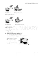
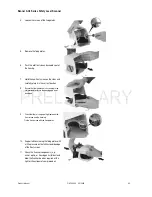
Страница 64: ...in two steps 1 Change the front screen 2 Calibrate the front screen When replacing the Scanner front screen due to contamination or similar Perform all work in a dust free environment if possible Do...

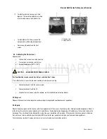
Страница 65: ...hat the rubber seal sits correctly in the slot provided for this in the housing and is not damaged 9 Check that there is no gap of light between the front screen and the housing Fix the front screen w...

Страница 66: ...nterface X1 with the control system Connect interface X2 with the PC Calibrate the front screen using the software see AG4soft Software Instruction Manual 8 5 Disposal Dispose of Scanner that can no l...

Страница 67: ...ty outputs or switching function are switched off 0 2 x 1 1 0 2 x 1 Boot process configuration process Safety outputs or switching function are switched off Data comparison with ConfigPlug 0 1 1 0 Obj...

Страница 68: ...t on the field pair control inputs ON Active WF is selected Flashes 2 Hz Front screen is dirty 2 yellow Flashes 4 Hz ConfigPlug configuration is not compatible with the Scanner 3 red ON Safety outputs...

Страница 69: ...ond with the ConfigPlug s configuration 1 0 1 0 1 Device fault Safety outputs or switching function are switched off Errors on the field pair control inputs Check the field pair switchover switchover...

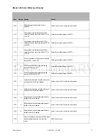
Страница 70: ...eck the interface parameters and start the transfer again 302 2 Interface X2 time specifications not complied with send data not acknowledged Check the interface parameters and start the transfer agai...

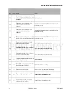
Страница 71: ...he connection wiring of the OSSDs 1111 9 Short circuit of one safety output or switching function OSSD with 24 V DC Check the connection wiring of the OSSDs 1606 4 Angle error detected poss rotation o...

Страница 72: ...ff path switch off because of eye safety internal defect If reset is not successful contact customer service 1907 4 Angle error detected poss rotation of the sensor housing switch off and reset follow...

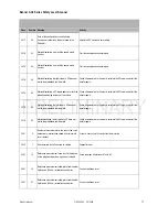
Страница 73: ...nitoring the left side of a PF does not match the predefined vehicle width Check all parameters in the wizard calculate the PFs again and start the transfer again 2018 50 MotionMonitoring the left sid...

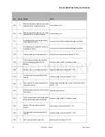
Страница 74: ...tivation of the PFs in the program wizard 2800 4 More than 2 PFs are activated during operation Check the activation of the control inputs FP1 FP4 2800 6 Unusable or defective control voltage for the...

Страница 75: ...l times Speed exceeding can no longer be corrected Check the activation of the PFs in the speed matrix and the speed the vehicle moved at 3402 3 Motion Monitor speed very much exceeded Exceeding canno...

Страница 76: ...Banner AG4 Series Safety Laser Scanner EC Declaration of Conformity Qualersonified P 76 P N 144924 05 2009 Product Manual...

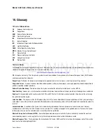
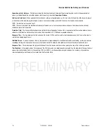
Страница 77: ...is feature allows the System to monitor the status of external devices such as MPCEs Fixed Guarding Screens bars or other mechanical barriers that prevent a person from entering or remaining in the da...

Страница 78: ...erson who enters the Protective Field reaches the machine and is specified in ISO 13855 and associated standards Response Time The time between the interruption by the System OSSDs and the instant whe...

Страница 79: ...Banner AG4 Series Safety Laser Scanner Product Manual P N 144924 05 2009 79...

Страница 80: ...Banner AG4 Series Safety Laser Scanner 80 P N 144924 05 2009 Product Manual...

Отзывы: