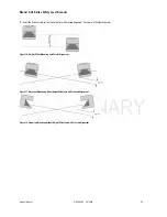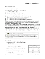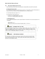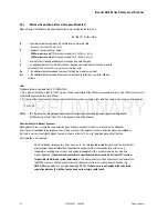
Banner AG4 Series Safety Laser Scanner
4.5.6
Example of separation distance formula adjustments Z
SM
Objects within the field (PF & WF) boundaries are detected using the laser pulse, time-of-flight measurement method. A measurement error
value,
Z
SM
, based on the farthest PF range value
R
G
, will need to be added to the minimum separation distance formula. Where this additional
factor is not possible, hard guards can be used to eliminate the hazard potential.
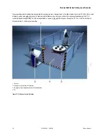
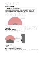
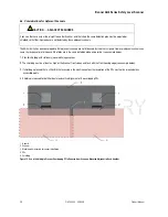
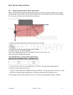
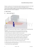
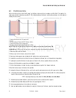
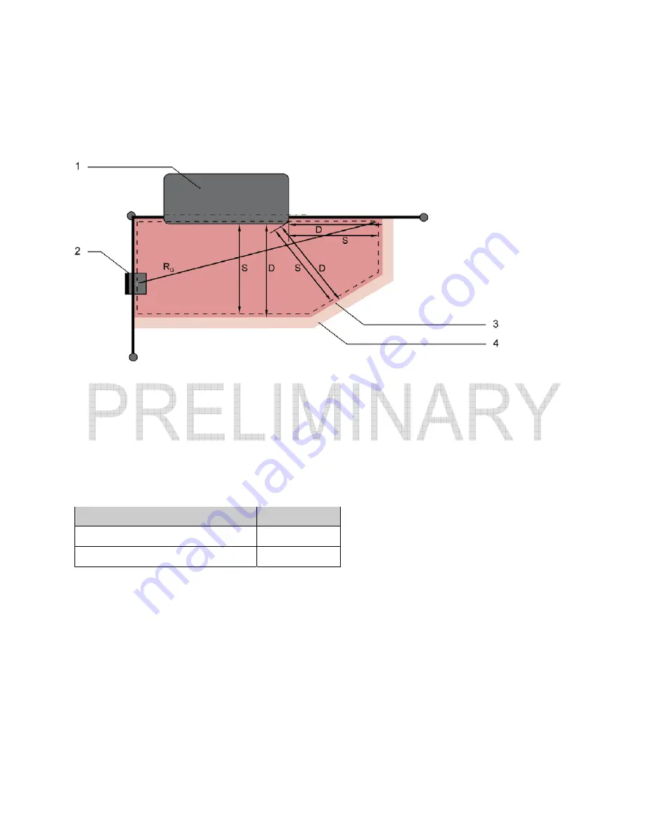
1 Routing machine where the PF boundary extends under the machine for a short distance
2 Scanner
3 PF
boundary
4 WF
boundary
S Calculated the minimum separation distance
S
(or
Ds
using US standards)
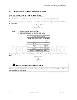
D In the figure above is
D
=
S
+
Z
SM
+ if required,
Z
REFL
R
G
Greater PF range without additional distances, measured from the rotation axis of the Scanner’s mirror
Figure 19. Defining the PF boundary for a horizontal field
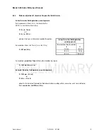
Table 3. Additional distance Z
SM
for PF contour because of measurement error
Largest PF radius R
G
without additional distances
Additional distance Z
SM
< 3.5 m
83 mm
≥
3.5 m
100 mm
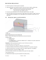
1.
Define the limits of the PF using the minimum separation distance “
S
” (or
Ds
for US standards) without an additional distance.
2.
Determine the longest PF range value
R
G
for this PF.
The longest PF range value determines the additional distance
Z
SM
see table above). The
R
G
distance extends from the rotary mirror's center
point to the farthest point of the protective field boundary. See the dimensional drawing for the AG4 axis reference marks.
3.
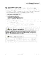
Avoid retro-reflectors at the beam level beyond the PF limit. If this is not possible, add another additional distance
Z
REFL
of
100 mm
.
Product Manual
P/N 144924 05/2009
35

