Banner AG4 Series Safety Laser Scanner
Product Manual
P/N 144924 05/2009
47
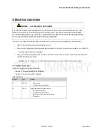
5.1.2
Interface assignment, plug X2
Plug X2 as RS 232 port
PIN
Signal
Description
1
- - -
Reserved
2
TxD
Data communication, send
3
RxD
Data communication, receive
4
- - -
Reserved
5 GND/shield
Ground/shield
6 RS
232
Reserved
7
N.C.
Do not assign
8
N.C.
Do not assign
9
Reserved
Reserved for test purposes
Figure 31. Plug X2 interface assignment as RS 232 port
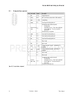
Plug X2 as RS 422 port
PIN
Signal
Description
1
Tx+
Data communication, send
2
Tx-
Data communication, send
3
Rx-
Data communication, receive
4
Rx+
Data communication, receive
5 GND/shield
Ground/shield
6
RS 422
Selection as interface RS 422 via jumper to pin 5
7
N.C.
Do not assign
8
NC.
Do not assign
9
Reserved
Reserved for test purposes
Figure 32. Plug X2 interface assignment as RS 422 port
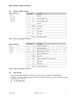
5.1.3
Cable Assembly
Either use the plug housing included with the Scanner and self-assemble the cables, or use Banner’s pre-assembled cables.
Control cables with ConfigPlug integrated in the plug are available as accessories. ConfigPlug saves an existing configuration and transfers
it automatically to the new Scanner.
Use only shielded cables.

