background image

If you select a position on the chart, the information window expands to include weather
details for the selected position.

Animating GRIB weather forecast

The GRIB data contains forecast information for a set number of days. It is possible to animate
the weather data and to show the predicted forecast for a specific time and date. The time
scales vary depending on the file you are using.
The time shift is shown in brackets in the GRIB information window. The time is relative to the
current time as provided by a GPS device connected to the system.
Select time and animation speed from the menu.

PredictWind weather and routing

For information about PredictWind weather and PredictWind routing, refer to 

"PredictWind"

 on

page 55.

SiriusXM weather

When connected to a Navico Weather module, you can subscribe and include Sirius audio
and Sirius Marine Weather Service on your system (North America only).
Depending on your selected subscription package, Sirius audio and weather service covers a
variety of North American inland waters and coastal areas. For more information refer to
www.siriusxm.com/marineweather

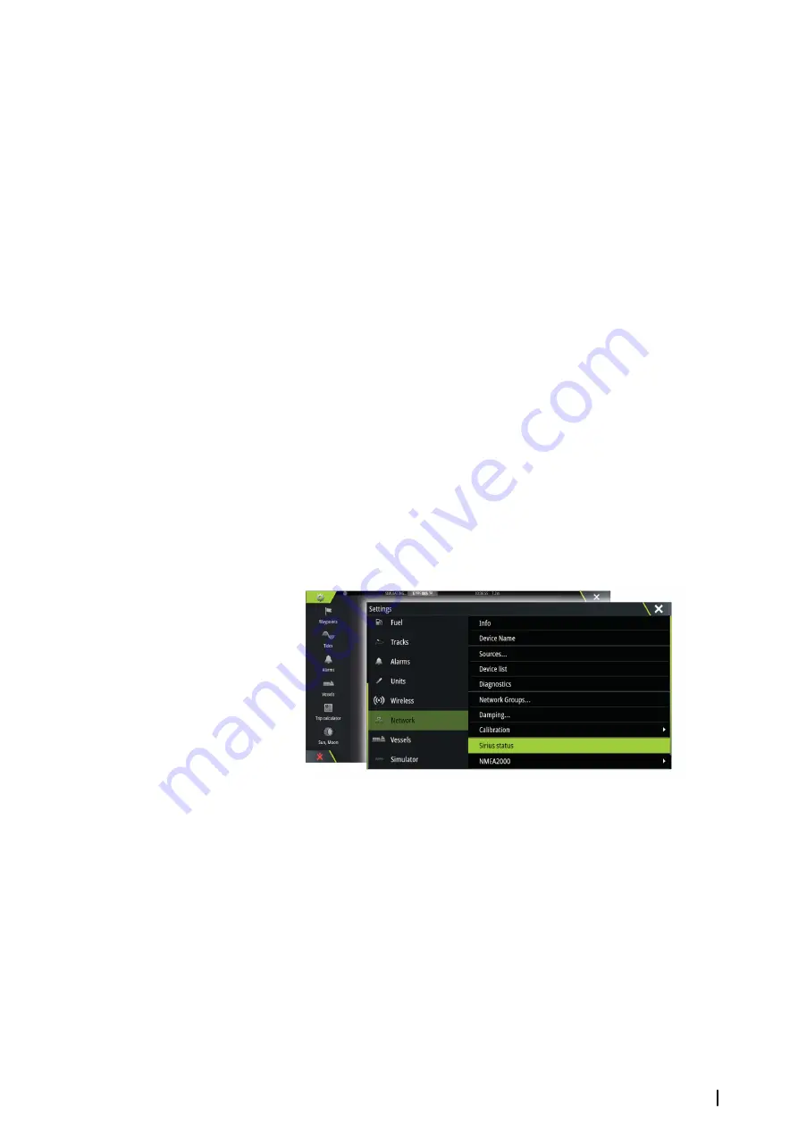
Sirius status panel

When the weather module is connected to the system, you get access to the Sirius status
panel.
The status panel shows signal strength is indicated as 1/3 (weak), 2/3 (good) or 3/3
(preferred). It also includes antenna status, service level, and the electronic serial number for
the weather module.

Sirius weather display

Sirius weather can be displayed as an overlay on your chart panel.
When weather overlay is selected, the chart menu increases to show the available weather
options.

Weather

| Zeus3 Operator Manual

119

Содержание Zeus3 Glass Helm

Страница 1: ...ENGLISH Zeus3 Operator Manual www bandg com ...

Страница 2: ......

Страница 3: ...ifications without notice Trademarks Navico is a registered trademark of Navico B G is a registered trademark of Navico Navionics is a registered trademark of Navionics Inc NMEA and NMEA 2000 are registered trademarks of the National Marine Electronics Association SiriusXM is a registered trademark of Sirius XM Radio Inc SimNet is a registered trademark of Navico Fishing Hot Spots is a registered ...

Страница 4: ...rnet connection to perform data downloads and uploads Internet usage via a connected mobile cell phone internet connection or a pay per MB type internet connection may require large data usage Your service provider may charge you based on the amount of data you transfer If you are unsure contact your service provider to confirm rates and restrictions About this manual The manual assumes that the u...

Страница 5: ... Turn the rotary knob Panning on the page Drag finger on the screen in any direction Zoom In Out Use pinch or spread gestures Exit the PDF viewer Press the X key or select the X in the upper right corner of the panel The Software version The software version currently on this unit can be found in the About dialog The About dialog is available in the System Settings For information regarding upgrad...

Страница 6: ...Configuring the WheelKey 20 Customizing the long press feature 20 Adjusting panel size 21 Password protection 21 Adding new favorite pages 22 Edit favorite pages 22 Setting the appearance of the Instrument bar 23 Charts 23 The Chart panel 23 Chart data 24 Showing dual chart types 24 Panning the chart 24 Chart scale 24 Vessel symbol 24 Positioning the vessel on the chart panel 25 Displaying informa...

Страница 7: ... Wind Plot panel 55 PredictWind 55 PredictWind weather 59 PredictWind weather routing and departure planner 62 Autopilot 62 Safe operation with the autopilot 62 Activating the autopilot 62 Switching from automatic mode to manual steering 62 Autopilot indication on the pages 63 The Autopilot panel 64 Autopilot modes 64 Standby mode 64 Non Follow Up NFU Power steering 64 Follow up steering FU 64 AUT...

Страница 8: ...mage 92 Using the cursor on the StructureScan panel 93 Saving waypoints 93 Viewing StructureScan history 94 Setting up the StructureScan image 94 Advanced StructureScan settings 96 StructureMap 96 The StructureMap image 96 Activating Structure overlay 96 StructureMap sources 97 StructureMap tips 97 Recording StructureScan data 97 Using StructureMap with mapping cards 97 Structure options 99 Forwar...

Страница 9: ...weather 119 PredictWind weather and routing 119 SiriusXM weather 122 Weather alarms 123 Video 123 The Video panel 123 Setting up the video panel 123 FLIR camera control 125 Alarms 125 Alarm system 125 Type of messages 125 Single alarms 125 Multiple alarms 125 Acknowledging a message 125 Alarms dialog 127 Tools 127 Waypoints 127 Tides 127 Alarms 127 Settings 127 Vessels 127 Sun Moon 127 Trip calcul...

Страница 10: ...ng the display unit 131 Cleaning the media port door 131 Checking the keys 131 Checking the connectors 131 NMEA Data logging 132 Software upgrades 133 Backing up your system data 10 Contents Zeus3 Operator Manual ...

Страница 11: ...enu 5 Rotary knob turn to zoom or scroll the menu press to select an option 6 Enter key press to select an option or to save settings 7 Exit key press to exit a dialog return to previous menu level and clear the cursor from the panel 8 MOB press simultaneously the Enter and Exit keys to create a MOB at the vessel s position 9 Arrow keys press to activate the cursor or to move the cursor Menu opera...

Страница 12: ...ogs used for carrying out a task or for browsing stored information 4 Favorites Select a button to display the panel combination Press and hold a favorite button to enter edit mode for the Favorites panel 5 Close button Select to exit the Home page and return to the previous active page 6 Power button Select to power off the unit 7 Man Over Board MOB button Select to save a Man Over Board MOB wayp...

Страница 13: ...down from top of the screen 7 Status bar 8 Dialog Information to or input from the user 9 Alarm message Displayed if dangerous situations or system faults occur 10 Menu Panel specific menu Split pages You can have up to 4 panels on each page 2panelspage 3panelspage 4panelspage Panel sizes in a split page can be adjusted from the System Controls dialog Pre configured split pages Each full screen ap...

Страница 14: ...tion FLIR camera integration If a FLIR M series camera is available on the Ethernet network you can display the video and control the camera from the Zeus The FLIR camera is controlled from the Video panel and no additional icons appear on the Home page Refer to Video on page 123 for more information BEP CZone integration The Zeus integrates with BEP s CZone system used for controlling and monitor...

Страница 15: ...documentation is provided with the H5000 system Refer to this documentation for how to install and configure the H5000 system Remote controllers You can connect a remote controller to the network and remotely control the unit To find out which remote controllers can be used refer to the product web page at www bandg com A separate manual is included with the remote controller Introduction Zeus3 Op...

Страница 16: ...Note If the unit is configured as a slave you cannot power off the unit by the Power key and the System Controls dialog does not display the power off option First time startup When the unit is started for the first time or after a factory default the unit displays a setup wizard Respond to the setup wizard prompts to select some fundamental setup options You can perform further setup using the sy...

Страница 17: ... Touchscreen operation Basic touchscreen operation on the different panels is shown in the table below The panel sections in this manual have more information about panel specific touchscreen operation Icon Description Tap to Activate a panel on a multi panel page Position the cursor on a panel Select a menu and a dialog item Toggle a checkbox option on or off Show basic information for a selected...

Страница 18: ...s are automatically displayed when required for entering user information in dialogs You operate the keyboard by selecting the virtual keys and you confirm your entry by selecting the virtual Enter key or by pressing the rotary knob A dialog is closed by saving or cancelling the entry A dialog can also be closed by selecting the X in the dialog s upper right corner or by pressing the X key Selecti...

Страница 19: ...continues to show navigation information to the initial MOB waypoint Navigation to subsequent MOB waypoints needs to be done manually Cancel navigation to MOB The system continues to display navigational information towards the MOB waypoint until you cancel the navigation from the menu Delete a MOB waypoint 1 Select the MOB waypoint to activate it 2 Tap the MOB waypoint s pop up or press the Enter...

Страница 20: ...tem Setting dialog Select the Short press option or Long press option in the WHEELKEY CONFIGURATION dialog and then an option from the list displayed Customizing the long press feature Use the Advanced settings dialog to specify if the long press on the panel opens the menu or displays the cursor assist feature on the panel Adjusting panel size You can change the panel size for an active split pag...

Страница 21: ...l or System Controls dialog Alarms activated from the Tools panel Files activated from the Tools panel GoFree Shop activated from the Tools panel Settings activated from the Chart menu under Chart Options You set and remove password protection from the system Settings dialog Adding new favorite pages 1 Select the New icon in the favorite panel on the Home page to open the page editor dialog 2 Drag...

Страница 22: ...nt bars You can turn the Instrument bar off from the System controls dialog Ú Note This only turns the Instrument bar off for the current page Turning the Instrument bar on off 1 Activate the System controls dialog 2 Deactivate activate the instrument bar icon to toggle the bar on and off Edit the content of the Instrument bar 1 Activate the Instrument bar by selecting it 2 Select the MENU button ...

Страница 23: ...tography depending on region All units support Insight charts from Navico including Insight Genesis The system also supports charts from Navionics and C MAP as well as content created by a variety of third party mapping providers in the AT5 format For a full selection of available charts visit www gofreeshop com www c map com or www navionics com Ú Note In this manual all possible chart menu optio...

Страница 24: ... the screen Select the Clear cursor menu option or press the X key to remove the cursor and cursor window from the panel This also centers the chart to the vessel position Chart scale You zoom in and out on the chart by using the zoom panel icons the rotary knob or by using 2 fingers to pinch zoom out and spread zoom in Chart range scale and range rings interval when turned on are shown in the low...

Страница 25: ...el position Select the Restore cursor menu option to display the cursor in its previous location The Clear cursor and Restore cursor options are useful features for toggling between the vessel s current location and the cursor position GoTo cursor You can navigate to a selected position on the image by positioning the cursor on the panel then using the Goto Cursor option in the menu The cursor ass...

Страница 26: ... on the panel by doing the following Pressing the rotary knob Pressing the Mark key Using the new waypoint option in the menu Creating routes You can create routes as follows on the chart panel 1 Position the cursor on the chart panel 2 Select New followed by New route in the menu 3 Tap the chart panel to position the first routepoint 4 Continue positioning the remaining routepoints 5 Save the rou...

Страница 27: ...n about SonarChart Live see section SonarChartLive on page 30 PredictWind weather and routing For information about PredictWind weather and PredictWind routing refer to PredictWind on page 55 Insight and C MAP charts All possible menu options for Insight and C MAP charts are described below The features and menu options available can vary depending on the charts you use This section shows menus fr...

Страница 28: ...y described in this section are common for all chart types Presentation The charts can be displayed in different imagery styles Shadedrelief Nocontours Rasterimagery Highresolutionbathymetry Shaded relief Shades seabed terrain No contours Removes contour lines from the chart Raster charts Changes the view to that of a traditional paper chart Raster transparency Controls the transparency of raster ...

Страница 29: ... regions and cartography versions You can view photo overlays in either 2D or 3D modes NoPhotooverlay Photooverlay landonly FullPhotooverlay Photo transparency The Photo transparency sets the opaqueness of the photo overlay With minimum transparency settings the chart details are almost hidden by the photo Minimumtransparency Transparencyat80 Depth palette Controls the Depth palette used on the ma...

Страница 30: ...the appropriate Navionics charts or chart card inserted For more information on what is required for these features refer to www navionics com Navionics specific chart options Orientation Look ahead 3D and change Chart source previously described in this section are common for all chart types Community edits Toggles on the chart layer including Navionics edits These are user information or edits u...

Страница 31: ...er time Dynamictideinformation Dynamiccurrentinformation The following icons and symbology are used Current speed The arrow length depends on the rate and the symbol is rotated according to flow direction Flow rate is shown inside the arrow symbol The red symbol is used when current speed is increasing and the blue symbol is used when current speed is decreasing Tide height The gauge has 8 labels ...

Страница 32: ...vionics com Fishing range Select a range of depths between which Navionics fills with a different color This allows you to highlight a specific range of depths for fishing purposes The range is only as accurate as the underlying chart data meaning that if the chart only contains 5 meter intervals for contour lines the shading is rounded to the nearest available contour line NoDepthhighlightrange D...

Страница 33: ...it is drawn without blue shading Ú Note The built in Navionics database features data down to 20 m after which it is all white Contours depth Determines which contours you see on the chart down to the selected safety depth value Rock filter level Hides rock identification on the chart beneath a given depth This helps you to declutter charts in areas where there are many rocks located at depths wel...

Страница 34: ...od If no options are turned on for the vessel then no extension lines are shown for your vessel Your vessel heading is based on information from the active heading sensor and the COG is based on information from the active GPS sensor For other vessels COG data is included in the message received from the AIS system ForwardScan If you have ForwardScan and this option is selected the ForwardScan hea...

Страница 35: ...gth of the laylines Targets Defines the target for a given TWS True Wind Speed The targets can be read from an H5000 CPU Polar table live measurements manually entered upwind and downwind angles or from the targets table Laylines targets table Edit the targets table to specify Upwind True Wind Angle TWA Upwind Boat Speed BS Downwind TWA and Downwind BS values for different true wind speeds Accurat...

Страница 36: ...information about PredictWind routing refer to PredictWindweatherroutinganddeparture planner on page 59 SonarChart Live tide correction When selected the tide correction feature uses information from nearby tide stations if available to adjust the depth values used by SonarChart Live as the sonar is recorded Synchronize 2D 3D chart Links the position shown on one chart with the position shown on t...

Страница 37: ...point you want to move The waypoint icon expands to indicate that it is active 2 Activate the menu and select the waypoint in the menu 3 Select the move option 4 Select the new waypoint position 5 Press the Enter key or the rotary knob to confirm the new position The waypoint is now automatically saved at the new position Edit a waypoint You can edit all information about a waypoint from the Edit ...

Страница 38: ...nt is added between existing routepoints If you set the new routepoint outside the route the new routepoint is added after the last point in the route 4 Drag a routepoint to move it to a new position 5 Save the route by selecting the save option in the menu Ú Note The menu changes depending on the selected edit option All edits are confirmed or cancelled from the menu Delete a route You can delete...

Страница 39: ...route appears in preview mode and the legs are color coded to indicate safe or unsafe areas Navionics uses red unsafe and green safe while C MAP uses red unsafe yellow dangerous and green safe 4 Move any routepoints if required when the route is in preview mode 5 Select Keep to accept the routepoints positions 6 Eventually repeat step 2 Selection and step 3 if you want the system to automatically ...

Страница 40: ...5 Select the Bulk Insert button 6 Enter a list of waypoints separated by commas for example 21 22 23 24 7 Select Enter If the system finds more than one waypoint that has similar IDs it will choose one and advise you which one it has chosen If the system does not find a waypoint with a similar ID to what you entered then a dialog opens and informs you of the items it did not find 8 Optional Give t...

Страница 41: ...lled Tracks can be converted to routes from the Edit dialog From the factory the system is set to automatically track and draw the vessel s movement on the chart panel The system continues to record the Tracks until the length reaches the maximum points and then automatically begins overwriting the oldest points The automatic tracking function can be turned off from the Tracks dialog Creating new ...

Страница 42: ...ints Routes and Tracks dialogs give access to advanced edit functions and settings for these items The dialogs are accessed by selecting the Waypoints button on the Tools panel on the Home page 42 Waypoints Routes and Tracks Zeus3 Operator Manual ...

Страница 43: ... route from current vessel position Starting a route from the chart panel Activate a route on the panel and then select the route navigation option from the menu You can select a routepoint to start navigating from a selected position Start navigating a route from the Route dialog You can start navigating from the Route dialog activated by Selecting the Waypoint tool from the Home page and then th...

Страница 44: ... this limit an alarm is activated Arrival alarm When the arrival alarm is enabled an alarm is activated when the vessel reaches the waypoint or when it is within the specified arrival radius Magnetic variation Magnetic variation is the difference between true bearings and magnetic bearings caused by different locations of the Geographic and the Magnetic north poles Any local anomalies such as iron...

Страница 45: ...ferred station for waypoint entry cursor position and position panel The graphic example shows a cursor position window with Loran position information For more information refer to your Loran system documentation Navigating Zeus3 Operator Manual 45 ...

Страница 46: ...r you get to the exact angle 8 Bearing to current waypoint 9 Active next waypoint ID routepoint ID or cursor 10 Rudder angle Ú Note Only visible if a valid rudder source is available on the system 11 Magnetic variation 12 Tide rate and relative direction Optional images You can turn the optional images on off from the menu Selecting data fields for the SailSteer panel Data sources connected to the...

Страница 47: ...and off in the Chart setting dialog Ú Note If both the SailSteer image and autopilot compass overlays are enabled then only the SailSteer overlay is shown Ú Note SailSteer overlay is not shown when the cursor is activate or when panning the chart Select the clear cursor option to display the SailSteer overlay again Ú Note If the Look ahead menu option is selected then the Heading up orientation mu...

Страница 48: ...0 CPU on your network start line data is calculated by the H5000 CPU Otherwise the data is calculated in the MFD Viewing the start line on the chart panel allows the navigator to assess around the starting area for hazards Use the laylines to see where the likely tracks into and out of the starting area will be relative to the chart data The solid black line indicates the start line between the tw...

Страница 49: ...ata numbers are calculated on the H5000 CPU and sent across the network There is only one start line If you set the start line on the MFD it will show on the H5000 Graphic Display and vice versa Ú Note Before setting the start line position it is important that the GPS Bow offset is updated to negate the difference between the GPS position and the bow of the vessel This setting is made in the Adva...

Страница 50: ...art panel and move the cursor to the position in the chart where you want the port end point to be 2 Open the menu and select Start line Port end and then Set at cursor 3 Repeat steps 1 and 2 for the starboard end point The start line end points are set and can be viewed on the Chart panel and Start line panel Setting end points at coordinates Select the Set coordinate Port and then the Set coordi...

Страница 51: ...line to the starboard start line end point 8 Advantage gained by starting at favored end 9 Port tack layline to the starboard start line end point 10 Race Timer 11 Starboard tack laylines to the port start line end point 12 Start Line bias angle 13 Port tack laylines to the port start line end point 14 Tide arrow relative to start line 15 Extension line 16 Distance to port end of start line In add...

Страница 52: ... wind or tide in current and future legs of the course Deselect Live and enter parameters for the wind tide or both to see how data might change for the leg For example if you can see the sea breeze building in with boats sailing different angles on the horizon you can enter this data to estimate the effect Race timer The race timer can be used to countdown to zero from a specified time ideal for c...

Страница 53: ... timer counts down If the start value is set to zero 00 00 when the timer is started the timer begins counting up recording the elapsed time To stop the timer from counting select Stop Reset Resets the timer to the start value If the timer is running when Reset is selected it continues to run from the start value Sync When the timer is counting down selecting Sync synchronizes the time up or down ...

Страница 54: ...ridging the missing data Selecting data Each data field can be changed to show the preferred data type and the time range 1 Select the edit option from the menu 2 Activate the field you want to edit 3 Change the information type and eventually the range 4 Save your changes The data available for the Time plots are by default the sources used by the system If more than one data source is available ...

Страница 55: ...y to overlay it on the chart refer to SpecifyPredictWindGRIBoverlay file on page 58 Download PredictWind files to a memory card connected to a PC and then import a file from the memory card into the unit s memory as follows Download PredictWind weather files to a memory card connected to a PC Note Do not use a map memory card Downloading files to a map card can corrupt the map card Insert the memo...

Страница 56: ...s To download a PredictWind weather file manually select the Download forecast option in the Chart menu to display the Select forecast type dialog Use the Select forecast type dialog to specify the type and area Ú Note To manually download data from PredictWind the unit must have an internet connection The Download forecast option is only available if you have turned on GRIB weather overlay on the...

Страница 57: ...ea rectangle you want to download GRIB weather for and choose the select menu option After you create your offshore area rectangle choose the Select menu option Specify the settings for the offshore lower resolution GRIB download refer to PredictWind downloadsettings on page 57 PredictWind download settings Model Allows you to select from the GRIB model options CMC Canadian Meteorological Centre a...

Страница 58: ...overlay file The Forecast menu option shows the GRIB file which is currently displayed on the chart If no file is displayed on the chart then the menu option does not show a GRIB file GRIBfiledisplayedonthechart NoGRIBfiledisplayedonthechart Select the Forecast menu option to open the GRIB Weather dialog The GRIB Weather dialog shows which GRIB file is currently displayed as overlay on the chart a...

Страница 59: ...the optimal route is as accurate as possible Set up and usage 1 Connect your unit to the internet Refer to Connectanddisconnectfromawirelesshotspot on page 103 2 Enter your PredictWind credentials in the PredictWind settings dialog 3 Launch the PredictWind routing feature the following options are available Route to cursor a Activate the cursor on the chart b Select the PredictWind menu option c S...

Страница 60: ... the Edit Route dialog Select the Route on the chart This lists the selected route in the menu Select the route in the menu and then Details in the expanded menu to open the Edit Route dialog b Select PredictWind to specify routing information For specifying details refer to PredictWindRoutingdialogoptions on page 60 c Select Download to request a new route from PredictWind If there is an internet...

Страница 61: ... forecast information from PredictWind Routing and destination forecast details are provided in the Summary panel Download Management To view the status of any ongoing route downloads select the Files icon on the Tool panel and then Transfers to see transfer status When a download completes the route is drawn on the chart Old routes are deleted when the new route becomes available If a route is be...

Страница 62: ... human navigator Activating the autopilot Switching from automatic mode to manual steering You switch the autopilot to STBY mode from any automatic operation mode from the autopilot pop up or using a physical standby key Autopilot indication on the pages 1 Autopilot indication in Status bar 2 Autopilot pop up 3 Autopilot tile in Instrument bar Autopilot mode indication in the Status bar The Status...

Страница 63: ...SAIL in the Autopilot Commissioning dialog instead the tack gybe feature is implemented Refer to TackinginAUTOmode on page 64 and TackinginWINDmode on page 67 Autopilotcontroller Modeselection Turnpatternselection Autopilot tile in Instrument bar You can select to show the autopilot tile in the Instrument bar If the autopilot pop up is turned off you can turn it on by selecting the tile in the Ins...

Страница 64: ...u select FU mode from the autopilot pop up Ú Note If the autopilot pop up is closed or if an alarm dialog is activated on the unit controlling the autopilot in FU mode the autopilot automatically changes to Standby mode Warning While in FU mode you cannot take manual control of the wheel AUTO mode auto compass In AUTO mode the autopilot issues rudder commands required to steer the vessel automatic...

Страница 65: ...ging If you need to avoid an obstacle when using NoDrift mode you can set the autopilot to Standby mode and power steer or use the helm until the obstacle is passed If you return to NoDrift mode within 60 seconds you can select to continue on previous set bearing line If you do not respond the dialog disappears and the autopilot goes to NoDrift mode with current heading as set bearing line NAV mod...

Страница 66: ...waypoint circle with radius 0 09 Nm Ú Note The distance between any waypoints in a route must not be smaller than the radius of the waypoint arrival circle WIND mode Ú Note The WIND mode is only available if the system has been set up for sailboat in the Autopilot Commissioning dialog Before the WIND mode is started it must be verified that valid input from wind transducer is available Initiate wi...

Страница 67: ...make it as quick as possible within control Turn pattern steering The autopilot includes a number of automatic turn steering features when the autopilot is in AUTO mode Ú Note The turn steering option is not available if the boat type is set to SAIL in the Autopilot Commissioning dialog instead the tack gybe feature is implemented Initiating a turn You start the turn by selecting the relevant turn...

Страница 68: ...w 90 turn Lazy S turn Makes the vessel yaw around the main heading You set the selected heading change before the turn is started During the turn you can alter the main heading the heading change and the turn radius from within the turn dialog Depth contour tracking DCTTM If the system has Echosounder input the autopilot can be set to follow a depth contour Warning Do not use this feature unless t...

Страница 69: ...8 control unit only one control unit can be active at the same time An inactive control unit is indicated with a square with a cross symbol in autopilot controller pop up Locking remote stations The AP24 AP28 includes a Remote Lock function that disables autopilot control from other units A locked control unit is indicated with a key symbol in autopilot controller pop up When the remote lock funct...

Страница 70: ...five consumes the most power and has the highest response The performance mode is indicated in the top left corner of the autopilot page Steering H5000 This option allows for manually changing parameters that were set during the commissioning of the autopilot computer For more details of the settings refer to the separate documentation for the autopilot computer Automatic response controls the rat...

Страница 71: ...on Follow up steering Off course Defines the limit for the off course alarm Manual speed If neither boat speed or SOG data is available and or deemed reliable a manual value for speed source can be entered and used by the autopilot to aid steering calculations Sailing H5000 Wind mode Select what wind function the autopilot will use when in wind mode Auto If TWA is 70º Wind mode will use AWA If TWA...

Страница 72: ...osition Actual Maintains the rudder offset Rudder limit Determines the maximum rudder movement in degrees from midship position that the autopilot can command the rudder in the automatic modes The Rudder limit setting is only active during autosteering on straight courses NOT during course changes Rudder limit does not affect Non Follow up steering Off heading limit Sets the limit for the off head...

Страница 73: ...Installation Used for autopilot installation and commissioning See the separate Zeus Installation manual Autopilot Zeus3 Operator Manual 73 ...

Страница 74: ...enu or individually as described in Radarsettingspanel on page 82 Dual radar You can connect to any combination of two supported radars and see both radar images at the same time Ú Note Interference will be seen on the Broadband Radar on most ranges when a pulse and a Broadband radar are transmitting at the same time on the same boat We recommend to only transmit on one radar at a time For example...

Страница 75: ... chart panel Activate one of the chart panels and then select one of the available radars in the radar source menu option Repeat the process for the second chart panel with radar overlay and select an alternative radar for this panel Radar operational modes The radar s operational modes are controlled from the Radar menu The following modes are available Power off The power to the radar scanner is...

Страница 76: ...covering details with your finger Activate the cursor on the panel then press and hold your finger on the screen to switch the cursor symbol to a selection circle appearing above your finger Without removing your finger from the screen drag the selection circle to the desired position When you remove your finger from the screen the cursor reverts to normal cursor operation Saving waypoints A waypo...

Страница 77: ...es predefined Sea clutter settings for harbor and offshore conditions in addition to the manual mode where you can adjust the settings You select Sea clutter modes from the menu or by a long press on the rotary knob You can only adjust the Sea clutter value in manual mode Rain clutter Rain clutter is used to reduce the effect of rain snow or other weather conditions on the radar image The value sh...

Страница 78: ...educes radar bandwidth to make targets appear larger in range and increase radar sensitivity Radar view options Radar symbology Radar symbology defined in the Radar Settings panel can be turned on off collectively See the radar panel illustration showing optional radar items Target trails You can set how long the trails generated from each target on your radar panel remain You can also turn OFF ta...

Страница 79: ...on your vessel and moving targets move across the Radar screen as you travel All stationary objects remain in a fixed position When the vessel s symbol reaches the edge of the screen the radar image is redrawn with the vessel symbol repositioned in the center of the screen When True motion is selected the menu expands to include a reset true motion option This allows for manually resetting the rad...

Страница 80: ...zones then select one of the guard zones 3 Select the shape for the zone The adjustment options depend on the guard zone shape 4 Select Adjust to define the settings for the guard zone The values can be set from the menu or by dragging on the radar panel A Bearing relative to the vessel heading B Depth C Range relative to vessel center D Width 5 Select the save option to save your settings When po...

Страница 81: ...argets are being tracked the radar menu expands to include options for cancelling individual targets or to stop the tracking function Cancel tracking individual targets by selecting the target icon before activating the menu Viewing MARPA target information If the pop up is activated you can select a MARPA target to display basic target information Information for the 3 MARPA targets closest to th...

Страница 82: ...ranged with the most dangerous targets on top You can select to show MARPA targets on top and before any AIS targets even if the AIS targets are closer to your vessel MARPA settings You can define the length of the MARPA trail making it easier to follow target movement A circle can be added around your vessel to present the danger zone The radius of the ring is the same as the closest point of app...

Страница 83: ...r range 7 A Scope 8 Temperature graph 9 Zoom bars 10 Range scale 11 Depth line 12 Bottom Optional Echosounder items Ú Note You turn the optional Echosounder items on off individually Refer to Echosounder Viewoptions on page 88 Multiple Echosounder You can specify the Echosounder source for the image in the Echosounder panel You can display two different sources simultaneously using a split panel c...

Страница 84: ... Goto Cursor option in the menu The cursor assist function Ú Note The cursor assist function is available if it is enabled Refer to Customizingthelongpress feature on page 20 The cursor assist function allows for fine tuning and precision placement of the cursor without covering details with your finger Activate the cursor on the panel then press and hold your finger on the screen to switch the cu...

Страница 85: ... the image Use the Echosounder menu options to set up the image When the cursor is active some options on the Echosounder menu are replaced with cursor mode features Select Clear cursor to return to the normal Echosounder menu The range The range setting determines the water depth that is visible on the screen Frequency The unit supports several transducer frequencies Available frequencies depend ...

Страница 86: ...the source for the image in the selected panel You can display two different sources simultaneously using a split panel configuration Menu controls for each panel are independent The source can be the internal Echosounder another MFD on the Ethernet network or a Echosounder module To define sources refer to the separate Zeus Installation manual Ú Note Using two transducers at the same frequency ra...

Страница 87: ...o the water By default the ping speed is set to max It may be necessary to adjust the ping speed to limit interference or to adjust for specific fishing conditions Start recording log data You can start recording log data and save the file internally in the unit or save it onto a card inserted into the unit s card reader The record function is activated from the Advanced menu option When the data ...

Страница 88: ...ng allocated space available for recordings Stop recording log data Select Stop in the Recording Echo dialog to fully stop the recording of all echosounder data Ú Note If you have selected the Upload to Insight Genesis option and are connected to a wireless hotspot your recorded files are transmitted to Insight Genesis when you select Stop Viewing the recorded sounder data Both internally and exte...

Страница 89: ...aph The temperature graph is used to illustrate changes in water temperature When toggled on a colored line and temperature digits are shown on the Echosounder image Depth line A depth line can be added to the bottom surface to make it easier to distinguish the bottom from fish and structures A Scope The A scope is a display of real time echoes as they appear on the panel The strength of the actua...

Страница 90: ...display from the menu You can use the cursor on the image measure distance and set view options as on a live Echosounder image If more than one channel was recorded in the selected Echosounder file you can select which channel to display You exit the view function by selecting the X in the upper right corner Structure depth offset Setting for Structure transducers All transducers measure water dep...

Страница 91: ...s available for selection in the Source menu option For information about defining sources refer to the separate Zeus Installation manual For information about Source selection refer to Source on page 86 ForwardScan Installation Used for ForwardScan installation and setup Refer to the ForwardScansetup on page 101 Echosounder Zeus3 Operator Manual 91 ...

Страница 92: ...ture 3 Frequency 4 Bottom 5 Zoom downscan Range sidescan icons 6 Range scale Zooming the StructureScan image You can zoom a StructureScan image by turning the rotary knob when the cursor is not active using the panel zoom icons by pinching or spreading on the screen Zoom level is shown on the upper left side of the panel Using the cursor on the StructureScan panel By default the cursor is not show...

Страница 93: ...n from the menu 3 Position the cursor on the second measuring point A line is drawn between the measuring points and the distance is listed in the Cursor Information panel 4 Continue selecting new measuring points if required You can use the menu to re position the start point and the end point as long as the measuring function is active When you select Finish measuring or press the X key the imag...

Страница 94: ... adjustment bar 2 Drag the bar or use the rotary knob to set the value Palettes You can select between several display palettes optimized for a variety of fishing conditions View You can set up the StructureScan page as a DownScan image left only right only or left right side scanning Pausing the StructureScan image You can pause the StructureScan image allowing you to examine the structures and o...

Страница 95: ...llation Range Lines Range lines can be added to the image to make it easier to estimate depth Downscan and distance SideScan Recording StructureScan data You can record StructureScan data and save the file internally in the Zeus unit or onto memory card as described in StartRecordingechosounderdata on page 87 StructureScan Zeus3 Operator Manual 95 ...

Страница 96: ...he chart screen as soon as Structure overlay is enabled 2 Select Structure source Live data is default Ú Note Structure overlay can also be activated by selecting a saved StructureMap file in the files browser StructureMap sources Two sources can be used to overlay Structure logs on the charts but only one can be viewed at a time Live data Used when StructureScan data is available on the system Sa...

Страница 97: ... be started from a StructureScan panel When StructureScan data is being recorded there is a flashing red symbol and a message appears periodically at the bottom of the screen Ú Note The message includes information about file size Keep the size of your logs to 100MB or less to allow for faster file conversion The recording is stopped by re selecting the record function Converting StructureScan dat...

Страница 98: ...e SideScan image on the map might be affected by the water depth Frequency Sets the transducer frequency used by the unit 800 kHz offers the best resolution while 455 kHz has greater depth and range coverage Noise rejection Signal interference from bilge pumps engine vibration and air bubbles can clutter the sonar screen The noise rejection option filters the signal interference and reduces on scr...

Страница 99: ...connect the ForwardScan transducer to the Sonar2 port on your Zeus unit leaving the Sonar1 port available for a CHIRP transducer Ú Note When a ForwardScan transducer connected to the Zeus is in use Transducers connected to Sonar1 port will be paused Warning Do not rely on this equipment as your principle source of navigation or hazard detection Warning Do not use this equipment to gauge depth or o...

Страница 100: ...story is shown behind the boat The higher the ratio the more history will be shown Point data By default ForwardScan only shows the bottom Select the Point data menu option to specify to view no sonar data points all sonar data points or only points Objects in the water column Show zones Displays warning zones yellow and critical zones red on the screen Refer to Criticalforward rangeandCriticaldep...

Страница 101: ...wardScan installation dialog Critical forward range and Critical depth Critical Forward Range and Critical Depth are user selected thresholds that define a critical zone forward of your vessel If you travel into water shallow enough to cross into the critical zone the Critical Zone alarm is activated You can display the critical warning zones by activating the Show zones menu option ForwardScan Ze...

Страница 102: ... in the transducer angle value can distort depth data increasing the risk of striking underwater obstructions Depth offset This is a value that can be entered on the Echo Installation page to make depth readings relate to any point from the water surface to the deepest point of the vessel Below are some alternative ways in which the offset can be entered Before setting the offset measure the dista...

Страница 103: ...hen Disconnect This changes the wireless mode to Access point mode In this mode you can connect a wireless device so that Apps such as GoFree Link can access the vessel s navigation information GoFree Shop The wireless must be connected to an external wireless hotspot in order to access the GoFree Shop At the GoFree Shop you can browse purchase and download compatible content for your system inclu...

Страница 104: ...ireless devices page in the Wireless settings dialog and then select the unit s Internal Wireless Next select the Mode option and then select Internal Access Point 2 Select a device on the Wireless devices page to view its Network Key 3 Navigate to the wireless network connection page on the smartphone and find the unit or GoFree wireless xxxx network If more than one is in range review the Wirele...

Страница 105: ...ice provides additional detail To view and change internal wireless detail values Network Name SSID Network Key or Channel the internal wireless must be in Access Point Internal Wifi mode To select a network hotspot to connect to the internal wireless must be in Client Mode Use the Mode option to change modes Client settings Displays information about the wireless hotspot your unit is connected to...

Страница 106: ...line A target is defined as dangerous based on the CPA and TCPA settings Refer to Definingdangerousvessels on page 110 Lost AIS target When no signals have been received within a time limit a target is defined as lost The target symbol represents the last valid position of the target before the reception of data was lost Selected AIS target activated by selecting a target symbol The target returns...

Страница 107: ... you can initiate a DSC call to other vessels from the Zeus The call option is available in the AIS Vessel Details dialog and in the Vessel status dialog activated from the Tools panel From the Call dialog you can change channel or cancel the call The Call dialog is closed when the connection is established AIS SART When an AIS SART Search and Rescue beacon is activated it starts transmitting its ...

Страница 108: ...e Vessels list Save the waypoint The waypoint is saved to your waypoint list This waypoint name is prefixed with MOB AIS SART followed by the unique MMSI number of the SART For example MOB AIS SART 12345678 Activate the MOB function The display switches to a zoomed chart panel centered on the AIS SART position The system creates an active route to the AIS SART position Ú Note If the MOB function i...

Страница 109: ...m will be activated when a message is received from an AIS target Vessel settings Your vessel s MMSI number You need to have your own MMSI Maritime Mobile Service Identity number entered in the system to receive addressed messages from AIS and DSC vessels It is also important to have the MMSI number entered to avoid seeing your own vessel as an AIS target on the chart Ú Note The Vessel message opt...

Страница 110: ...luded in the message received from the AIS system Defining dangerous vessels You can define an invisible guard zone around your vessel When a target comes within the set limits the symbol changes to the Dangerous target symbol An alarm is triggered if activated in the Alarm settings panel Speed and course indication The extension line can be used to indicate speed and course for targets either as ...

Страница 111: ...s e g CZone are present on the network Customizing the Instruments panel You can customize the Instruments panel by changing the data for each of the gauges in the dashboard by changing the dashboard layout and by adding new dashboards You can also set limits for analog gauges All edit options are available from the Instruments panel menu Available editing options depend on which data sources are ...

Страница 112: ...our selected subscription package For more information refer to www siriusXM com Before you can start using your audio equipment it must be installed according to the Zeus Installation manual and to the documentation included with the audio device Enabling audio A compatible audio device connected to the NMEA 2000 network should automatically be identified by the system If not enable the feature f...

Страница 113: ...vices and then select Pair The SonicHub 2 connects to the paired device Connecting and disconnecting paired devices The SonicHub 2 automatically connects to a device when you pair them You can pair it to several devices but only one device can be connected at a time You can manually disconnect and connect the SonicHub 2 to paired devices To disconnect a paired device select the paired device in th...

Страница 114: ...udio tile 4 Audio tools Audio control buttons Icon Tuner VHF DVD Playback Select to display the list of available sources Select to select previous next frequency Press and hold to tune in a channel Select to rewind play fast forward Select to select previous next track Select to select next previous favorite channel N A N A N A N A Select to start N A N A Select to pause playback Select to displa...

Страница 115: ... zone Adjustments to the bass and tremble settings will alter all zones Master volume control By default the volume for all speaker zones are adjusted when you adjust the volume You can define which zones will be altered when you increase decrease the volume Selecting tuner region Before playing FM or AM radio and using a VHF radio you must select the appropriate region for your location Detaching...

Страница 116: ...t The favorite channels can be viewed selected and deleted from within the Favorite list You page through favorite channels by using the up down audio panel buttons Sirius radio North America only Channels list The channels list displays all available Sirius channels whether or not you have a subscription for the channel Favorites list You can create a list of your favorite Sirius channels from wi...

Страница 117: ... small barb 35 knots and 60 knots indicated with 1 x arrow barb 1 x large barb Windspeed 35knots Windspeed 60knots Showing weather details If pop up is enabled you can select a weather icon to display the identity of the observation If you select the pop up detailed information about the observation is displayed You can also display the detailed information from the menu when the weather icon is s...

Страница 118: ...ases to show GRIB weather options From this menu you can select which weather symbols you want to display set the distance between the barbs and adjust the opaqueness of the weather symbols From this menu you can also animate the weather forecast Refer to AnimatingGRIBweather forecast on page 119 The Forecast menu option displays the GRIB file currently in memory and overlaid on the chart Select t...

Страница 119: ...on page 55 SiriusXM weather When connected to a Navico Weather module you can subscribe and include Sirius audio and Sirius Marine Weather Service on your system North America only Depending on your selected subscription package Sirius audio and weather service covers a variety of North American inland waters and coastal areas For more information refer to www siriusxm com marineweather Sirius sta...

Страница 120: ...r bar is shown on the left side of the display You define how the color codes are used to identify sea surface temperature See Adjusting colorcodes on page 122 Wave indication Colors are used to indicate forecasted wave height The highest waves are dark red while the lowest are blue You can define how the color codes are used to identify the wave height Refer to Adjusting colorcodes on page 122 Su...

Страница 121: ...ategory 1 5 tracking past grey present red future yellow Tropical disturbance depression tracking past grey present red future yellow Storm attributes Lightning Watch box location and warning Marine zone location Local weather Select the Local weather menu option to display the Local weather dialog This dialog shows weather forecast and alerts for the area Select a time slot tab to see the forecas...

Страница 122: ...n the system depends on the amount of weather activity the more complex it is the less time that is available for animation You can animate the past or the future depending on which weather view you have turned on With precipitation overlay you can animate for the past and only assume weather conditions in the immediate future With colored wave height overlay you can animate the future the predict...

Страница 123: ...SC and PAL video Check the local video standard or the standard of your cameras Adjusting the video image You can optimize the video display by adjusting the video image settings The settings are adjusted individually for each video source Default for all settings 50 FLIR camera control When the connection is established to a FLIR camera the menu changes to include access to FLIR camera controls Ú...

Страница 124: ... your selected FLIR camera source option Digital zoom Only available when the camera is in Infrared mode In this mode the zoom is represented in levels 0 2 and 4 times zoom Each press on a zoom button increments or decrements the zoom level Optical zoom Available in daylight mode In this mode the camera continues to zoom for as long as you press a zoom panel button The FLIR camera source options T...

Страница 125: ...arm as the title and with details for the alarm Multiple alarms If more than one alarm is activated simultaneously then the alarm message displays a list of up to 3 alarms The alarms are listed in the order they occur with the alarm activated first at the top The remaining alarms are available in the Alarms dialog Acknowledging a message The following options are available in the alarm dialog for ...

Страница 126: ...The alarm dialogs can also be activated from the Tools panel The alarm dialogs include information about active alarms and alarm history 126 Alarms Zeus3 Operator Manual ...

Страница 127: ...alarms Alarm history List of all alarms with time stamp Alarm settings List of all available alarm options in the system with current settings Settings Provides access to application and system settings Vessels Status listing List of all AIS MARPA and DSC vessels with available information Message listing List of all messages received from other AIS vessels with time stamp Sun Moon Displays sunris...

Страница 128: ...te The built in wireless functionality must be connected to an external wireless hotspot in order to access the GoFree Shop Refer to Connectanddisconnectfromawireless hotspot on page 103 Opens the GoFree Shop web site At the GoFree Shop you can browse purchase and download compatible charts for your system You can also upload your Echosounder logs to be shared on Social Map charts When you log on ...

Страница 129: ...e is running the demonstration pauses After a time out period demo mode resumes and any changed settings are restored to default Ú Note Demo mode is designed for retail showroom demonstrations Simulator source files You can select which data files are used by the simulator A set of source files is included in your system and you can import files by using a card inserted into the card reader You ca...

Страница 130: ...se or Simulated route Otherwise GPS data including speed and course come from the selected source file Set start position Moves your vessel to the current cursor position Ú Note This option is only available when the GPS source is set to Simulated course Sailing Opens dialog for selecting sail specific simulator data 130 Simulator Zeus3 Operator Manual ...

Страница 131: ... that the sun cover be fitted when the unit is not in use for an extended period Cleaning the media port door Clean the media port door regularly to avoid salt crystallization on the surface causing water to leak into the card slot Checking the keys Make sure that no keys are stuck in the down position If one is stuck wiggle the key to free it back to normal Checking the connectors The connectors ...

Страница 132: ...s file to assist in technical support enquiries To use the analyzer open the About page of the System settings dialog and select Support Two options are displayed Create report Analyzes your network and prompts you for information required for support and creates the report with information automatically gathered from the network You can add screenshots and log files that will be attached to the r...

Страница 133: ...uch information as the time and date when a route was created User Data File version 4 This is best used when transferring data from one system to another since it contains all the extra bits of information these systems store about items User Data file version 3 w depth Should be used when transferring user data from one system to a legacy product Lowrance LMS LCX User data file version 2 no dept...

Страница 134: ...tes and Tracks are stored in the display unit s memory until the data is purged This is necessary to allow user data to be synchronized across multiple units on an Ethernet network If you have numerous deleted unpurged Waypoints purging may improve the performance of your system Ú Note When user data is purged from the memory it cannot be recovered 134 Maintenance Zeus3 Operator Manual ...

Страница 135: ...ur tracking 68 Dodging 65 Follow up steering 64 Gybing 67 Indication in Status bar 62 Indication on pages 62 Locking remote stations 69 Modes 64 Non Follow up mode 64 Standby STBY mode 64 Switching to manual steering 62 Tacking in AUTO mode 64 Tacking in WIND mode 67 Turn pattern steering 67 Waypoint arrival circle 66 WIND mode 66 Autorouting see Dock to dock Autorouting 38 Autorouting Dock to doc...

Страница 136: ...ions 86 Using the cursor 84 View history 85 View options 88 View recorded data 88 Zoom bar 83 Zoom bars 89 Zooming 83 Echosounder Split Zoom 89 Export region 133 Extension lines 110 F Favorite pages 14 Adding new 21 Edit 22 Favorites 19 Files to a card copying 128 Files management 127 Files Viewing 128 Find items tool 128 First time startup Setup wizard 16 FLIR camera Controlling 123 Digital zoom ...

Страница 137: ... rejection 86 O Operation Touch 17 Overlay downscan 90 Overlay SailSteer on Chart 47 P Pages Selecting a page 18 Selecting active panel 18 Palettes 89 94 Panels Adjusting panel size 20 Password protection 21 PDF viewing files 4 Phantom Loran 44 Settings 45 Pin code Password protection 21 Ping speed 87 PPI 79 PredictWind Routing Summary info 61 PredictWind Weather routing 59 PredictWind Departure p...

Страница 138: ...nels 116 Sirius weather Animated weather graphics 122 Color codes 122 Marine zones 121 Overlay on chart panel 119 Precipitation 120 Sea Surface Temperature SST 120 Status panel 119 Tropical statements 122 Wave indication 120 Weather icons 121 SiriusXM weather 119 SL2 format 87 SL3 format 87 SLG format 87 Smartphone connection 104 Software upgrade 132 Software version 5 Software How to update 132 S...

Страница 139: ...Vessel settings 109 Video 123 Adjusting the image 123 Setting up the panel 123 Source 123 Standard 123 Video Video panel 123 View Echosounder log 90 Viewing files 128 W Wallpaper customizing 20 Warranty 4 Waypoints routes and tracks Purging 134 Waypoints routes trails and trips Export 133 Waypoints 37 Alarm settings 38 Delete 37 Dialog 42 Edit 37 Moving 37 Saving 26 37 76 Weather 117 Alarms 122 Sh...

Страница 140: ... 988 11377 001 0980 ...

Отзывы: