73
deutsch
73
E
M4
ca. 15
63
100
60
ca. 20
ca. 15
145
160
Head 2 Head 1
X1
X4
X2
X3
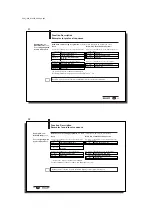
Mounting the
BIS C-6021
processor
BIS C-6021
Mounting Processor
The processor is mounted using 4 M4 screws.
C60_1-023_819395_0508_en.p65
74
74
E
Head 2 Head 1
X1
X2
X3
X4
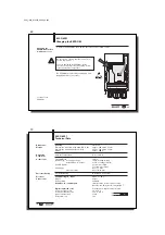
Connection for read/write head 2
Connection for read/write head 1
Connection diagram
for BIS C-6021
processor
I
NTER
B
US
output
I
NTER
B
US
input
Connection locations
and names
Digital input,
power supply for ST9
remote bus version
Function ground FE
BIS C-6021
Opening the processor / Wiring Diagrams
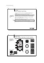
To convert the processor for the power supply via the installation remote bus instead of sup-
plying it via X1, the internal connections have to be changed.
Ensure that the device is turned off. Remove the 4 screws on the BIS C-6021 and lift off the
cover. Conversion see the following
.
Opening the
BIS C-6021
processor
Be sure before
opening that the
unit is disconnected
from power.
Mounting of the cover
(4 screws),
max. permissible tightening
torque: 0.15 Nm
Service interface


