15
deutsch
15
E
Input and Output
buffers
(continued)
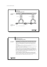
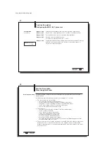
Example:
Using a PLC, the buffer sector for the BIS C-60_1 will start at input byte EB32 and
output byte AB 32.
Memory map:
PLC:
BIS:
Read/write head 1 (R/W1):
Head R/W 1
Input buffer
from EB 32 to EB 39
Subaddress 0
Output buffer
from AB 32 to AB 39
...
Subaddress 7
Read/write head 2 (R/W2):
Head R/W 2
Input buffer
from EB 40 to EB 47
Subaddress 0
Output buffer
from AB 40 to AB 47
...
Subaddress 7
EB 0 / AB 0
PLC
buffer
buffer
for R/W 1
buffer
for R/W 2
Function Description
In- and Output Buffer on I
NTER
B
US
Please note the
basic procedure on
13 and 28...35
and the examples on
pages
36...55.
☞
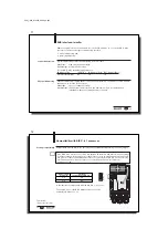
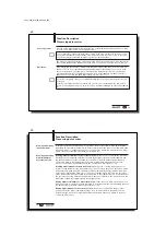
Note that these buffers can be in two different
sequences depending on the type of control.
The following description is based on sequence 1!
Sequence 1
Sequence 2
Subaddress 00
Subaddress 01
01
00
02
03
03
02
04
05
05
04
06
07
07
06
C60_1-023_819395_0508_en.p65
16
16
E
Configuration of the
output buffer for one
(1) read/write head
Function Description
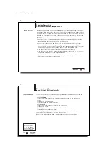
Output Buffer, Configuration and Explanation
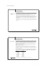
Sub-
Bit
Meaning
Function Description
address
Name
00
Hex
CT
Data carrier type Select data carrier type:
for data carrier type:
Bit Header
0
32 Byte block size
BIS C-1_ _-02, -03, -04, -05
1
64 Byte block size
BIS C-1_ _-10, -11, -30
TI
Toggle-Bit In
for reading:
Controller is ready to accept
new/additional data.
for writing:
Controller has prepared
new/additional data.
GR
Ground state
Causes the BIS system to go to ground state.
AV
Command
Signals the ID system that a job is waiting.
(continued next )
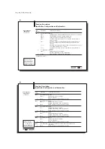
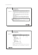
Description of
Output buffer
Bit No.
7
6
5
4
3
2
1
0
Subaddress
00
Hex
= Bit Header
CT
TI
GR
AV
Bit Name
01
Hex
Command Designator
or
Data
or
Config. 1st byte
02
Hex
Start Address (Low Byte)
or
Data
or
Config. 2nd byte
03
Hex
Start Address (High Byte)
or
Data
or
Config. 3rd byte
04
Hex
No. of Bytes (Low Byte)
or
Data
or
Config. 4th byte
05
Hex
No. of Bytes (High Byte)
or
Data
or
Config. 5th byte
06
Hex
Data
or
Config. 6th byte
07
Hex
2nd Bit Header (as above)
or
Data
Please note the
basic procedure on
13 and 28...35
and the examples on
pages
36...55.


