


25
deutsch
25
E
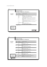
Function Description
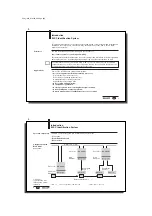
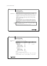
Configuring the BIS C-60_1 processor
Configuration,
Overview
The following functions can be activated / deactivated through the configuration:
– CRC_16 data check:
If this function is activated, the correctness of the read or written data is ensured by a
CRC_16 data check (see 9).
– Simultaneous data transmission for both read/write heads:
With simultaneous data transmission shorter read/write times can be achieved depending
on the amount of data to be read/written and the type of controller.
– Dynamic operation on Read/Write Head 1 or 2:
If dynamic operation is parametered, a read/write job can be sent even though there is no
data carrier in the active zone of the head. As soon as a data carrier passes by the head,
the command is immediately carried out.
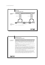
– "Auto-Read” for Read/Write Head 1 or 2:
If this function is activated, the processor reads out the first (max. 31) bytes from the data
carrier starting at a defined start address as soon as the carrier enters the active zone of
the read/write head. The start address must first have been stored in the processor’s
EEPROM with the command ID 07
Hex
.
– 2nd bit header at end of in- and output buffer:
The 2nd bit header (factory setting) prevents data from being accepted by the bus as long
as it is not fully updated.
– Display state of the digital input in the bit header of the input buffer:
If this function is activated, the IN-bit displays the state of the digital input of the processor:
IN = 0
Õ
digital input low; IN = 1
Õ
digital input high
– Reset BIS C-60_1 processor through the digital input:
If this function is activated, the processor is reset when the digital input is set to high.
C60_1-023_819395_0508_en.p65
26
26
E
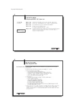
Function Description
Configuring the BIS C-60_1 processor
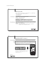
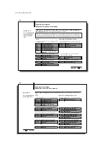
Configuration
The BIS C-60_1 processor is configured by the controller using the output buffer. The con-
figuration data are arranged within 6 configuration bytes that are sent to the BIS C-60_1
processor using the command identifier 04
Hex
(see Example 14 on 54). Command identifier
05
Hex
is used to read out the current device configuration (see Example 15 on 55).
To input the configuration, all 6 bytes must be entered in Hex. Only the named bits are permitted
to be changed. If any of the other bits are changed, there is no assurance that the BIS C-60_1
will function properly.
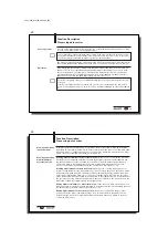
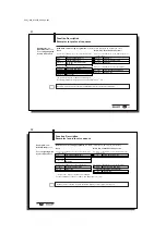
The default values of the 6 bytes are (factory setting):
1st byte
2nd byte
3rd byte
4th byte
5th byte
6th byte
Hex
00
80
00
82
00
00
Binary
000
0
0
0
00
100
00
000
00000000
10
0000
1
0
000
00
000
00000000
bit 3
bit 4
bit 7
bit 2 bit 4
bit 5
bit 5
bit 8
bit 5
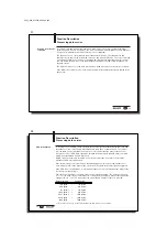
1st byte, bit 5
Activate CRC_16 data checking
1st byte, bit 3
Activate simultaneous data transmission
for both
read/write heads
2nd byte, bit 5
Dynamic mode on read/write head 1
(for effects on read/write times, see
56/57)
2nd byte, bit 4
Activate Auto-Read function starting at specified address after CT-Present
for Head 1 (the amount data read is 6 bytes for a double bit header or
7 bytes for a single bit header)
These are used for
configuration:
Having the following
functions:
Bit state: 0 = no
1 = yes