9
deutsch
9
E
BIS C-60_1 Processor
Basic knowledge for application
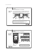
The processor writes data from the host system to the data carrier or reads data from the
carrier through the read/write head and prepares it for the host system. Host systems may
include:
–
a host computer (e.g. industrial PC) or
–
a programmable logic controller (PLC)
When sending data between the read/write head and the data carrier a procedure is required
for recognizing whether the data were correctly read or written.
The processor is supplied with standard Balluff procedure of double reading and comparing.
In addition to this procedure a second alternative is available: CRC_16 data checking.
Here a test code is written to the data carrier, allowing data to be checked for validity at any
time or location.
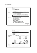
Advantages of CRC_16
Advantages of double reading
Data checking even during the non-active phase
(CT outside read/write head zone).
No bytes on the code tag need to be reserved for
storing a check code.
Shorter read times since each page is read only
once.
Shorter write times since no CRC needs to be
written.
Since both variations have their advantages depending on the application, the user is free to
select which method of data checking he wishes to use (see Parametering on 26 and 32).
It is not permitted to operate the system using both check procedures!
Control Function
Data checking
☞
C60_1-023_819395_0508_en.p65
10
10
E
I
NTER
B
US
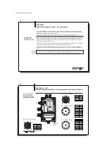
Communication between the BIS C-60_1 processor and the host system is via I
NTER
B
US
.
The I
NTER
B
US
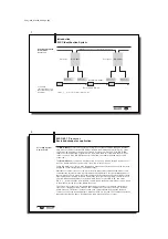
system consists of three components:
– the wiring module (rack card for industrial PC or PLC),
– Bus terminal as network node and/or
– the I/O modules (here the BIS C-60_1 processor).
Depending on the wiring module up to a maximum of 63 BIS C-60_1 processors can be
connected.
The BIS C-6001 processor is used as a remote bus station. The BIS C-6021 can be used as a
remote bus or installation bus station.
Important hints for use with PLC:
In some control systems the I
NTER
B
US
data area is not synchronously transmitted with the
updating of the input/output content. If more than 2 bytes of data are sent, a mechanism must be
used which guarantees that the data in the PLC and the data in the BIS C are always identical!
2nd alternative: Set 2nd bit header
Data exchange between PLC and BIS is controlled by the so-called bit header. This is always the
first byte of the respective read/write head in the data buffer. This bit header exists both in the
input range (data from BIS to the PLC) and in the output range (data from the PLC to the BIS). lf
this bit header is also sent as the last byte, a comparison of these two bytes can be used to
guarantee the consistency of the transmitted data.
In this method the PLC cycle is unaffected nor is the bus access time changed. All that is
required that a byte in the data buffer be used for the 2nd bit header instead of for user data.
This 2nd alternative is the Balluff recommended setting (factory default).
BUS interface: I
NTER
B
US
☞

