


Safety Considerations
WBPEEUI220771A0
3 - 3
4. If storing the auxiliary terminal prior to installation, leave it
in the original crate, if possible. Store in an area free from cor-
rosive vapors and extremes in temperature and humidity.
5. Do not store the auxiliary terminal in an area that would
take it out of the specifications listed in Table
Safety Considerations
It is critical to read, understand and heed all instructions,
warnings and cautions located throughout this instruction and
on the equipment itself. Only qualified personnel must be
allowed to install, operate, maintain and repair this equipment.
The auxiliary terminal was designed to allow installation with-
out anchoring; however, there is a possibility of tipping if stabi-
lizers are not installed. Be sure to stabilize the components
when removing any fasteners that secure them to their ship-
ping pallets. Never sit or stand on work surfaces or any other
part of the auxiliary terminal.
Do not remove or install printed circuit boards, or modules or
components containing them with power applied. This could
damage the circuit board. Remove power to all AC wiring when
removing or connecting AC wires to prevent injury to personnel
and equipment damage. To prevent equipment damage,
remove DC power to all DC wiring when removing or connect-
ing DC wires, circuit boards, or modules or components con-
nected to them.
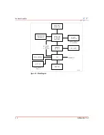
Wiring Considerations
This section discusses AC power wiring, communications wir-
ing and grounding for the auxiliary terminal. For the proce-
dures to accomplish these tasks, refer to the installation
sequence flowcharts at the end of this section for the path to
the proper procedure.
For detailed information on AC power distribution and system
grounding, refer to:
•
Содержание C-I-CV42C
Страница 1: ...Bailey Hartmann Braun TM Instruction Conductor Conductor VMS Series 42 Auxiliary Terminal ...
Страница 15: ...WBPEEUI220771A0 ...
Страница 43: ...WBPEEUI220771A0 ...
Страница 53: ...WBPEEUI220771A0 ...
Страница 67: ...WBPEEUI220771A0 ...
Страница 77: ...WBPEEUI220771A0 ...
Страница 93: ...PR1 2 WBPEEUI220771A0 Procedure 3 Turn each end latch turn 4 Open the door ...
Страница 97: ...WBPEEUI220771A0 ...
Страница 107: ...WBPEEUI220771A0 ...
Страница 113: ...WBPEEUI220771A0 ...
Страница 123: ...WBPEEUI220771A0 ...
Страница 125: ...WBPEEUI220771A0 ...
Страница 133: ...WBPEEUI220771A0 ...
Страница 137: ...WBPEEUI220771A0 ...
Страница 141: ...WBPEEUI220771A0 ...
Страница 143: ...WBPEEUI220771A0 ...
Страница 145: ...WBPEEUI220771A0 ...
Страница 147: ...WBPEEUI220771A0 ...
Страница 151: ...WBPEEUI220771A0 ...
Страница 177: ...PR27 6 WBPEEUI220771A0 Procedure 7 Install all cables onto the CPU ...
Страница 181: ...WBPEEUI220771A0 ...
Страница 184: ...Procedure WBPEEUI220771A0 PR29 3 Figure PR29 2 IIADP02 Bezel Removal T01401A REAR VIEW SCREWS 4 ADP ...
Страница 185: ...WBPEEUI220771A0 ...
Страница 195: ...WBPEEUI220771A0 ...
Страница 197: ...WBPEEUI220771A0 ...
Страница 213: ...WBPEEUI220771A0 ...


