


29
29
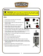
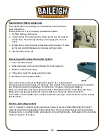
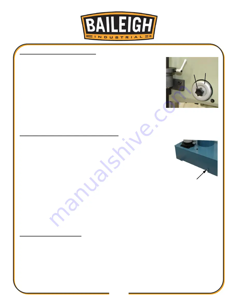
Spindle Return Spring Adjustment
The spindle return is preset by the manufacturer and should not
need adjustment.
If future attention is ever required, proceed as follows:
1. Do NOT remove spring cap.
2. Loosen screw (E) just enough to rotate spring cap (F) past pin
(Inside case. Not normally visible.) and engage pin into next
notch.
3. Rotate spring cap clockwise to decrease spring tension. Rotate
spring cap counterclockwise to increase spring tension.
4. Tighten both screws (E).
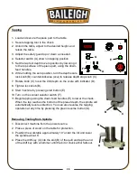
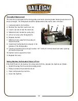
Accessing and Cleaning the Coolant System
1. Clean the drain screen.
2. Drain and wash out the dirt and debris from the reservoir
3. Replace coolant drain plug.
4. Thoroughly clean the pump and pump inlet
5. Re-fill tank with coolant solution.
The coolant system should be filled with 2 gallons of a cutting coolant.
Fill by pouring coolant into base of machine. Add coolant in the same manner when coolant is
low. Follow all coolant manufacturer’s instructions for safety, mixing and disposal.
Make sure drain hose has good, tight connection into table and that coolant flows into base.
Make sure hose leaving pump and entering ball valve has good, tight connections.
The flexible nozzle enables user to adjust coolant for each job. One ball valve controls coolant
flow to nozzle.
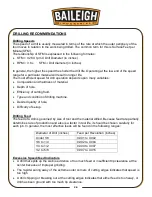
Oils for Lubricating Coolant
Any 10:1 (water to coolant) solution will work, however we recommend Baileigh B-Cool 20:1
(water to coolant) biodegradable metal cutting fluid. It has excellent cooling and heat transfer
characteristics, is non-flammable, and extends tool and machine life. Each gallon of concentrate
makes 21 gallons of coolant.
Drain
E
F
Содержание DP-1000VS
Страница 19: ...16 16 OVERALL DIMENSIONS ...
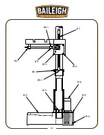
Страница 20: ...17 17 GETTING TO KNOW YOUR MACHINE Q F P J B C A G H I L M E F D N O K R ...
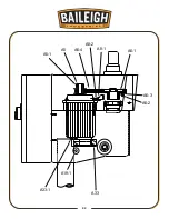
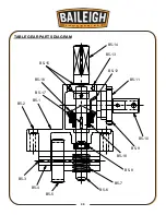
Страница 35: ...32 32 A6 2 A6 3 A6 1 A6 4 A8 1 A8 2 A5 A5 1 A33 1 A19 1 A33 ...
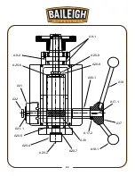
Страница 36: ...33 33 A20 7 A30 A17 2 A17 1 A17 A18 A18 1 A30 1 A20 9 A20 8 A9 1 A9 2 A20 6 A31 A32 A31 1 A20 5 A20 4 A20 2 ...
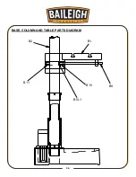
Страница 39: ...36 36 BASE COLUMN AND TABLE PARTS DIAGRAM B1 B2 B11 B10 B9 B10 1 ...
Страница 40: ...37 37 B3 B4 B6 1 B6 B5 1 B5 2 B8 B8 1 B12 B13 B16 B15 B14 ...
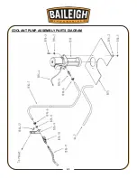
Страница 44: ...41 41 COOLANT PUMP ASSEMBLY PARTS DIAGRAM ...
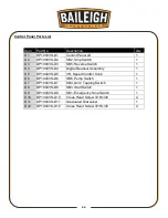
Страница 46: ...43 43 CONTROL PANEL PARTS DIAGRAM ...
Страница 48: ...45 45 CHUCK GUARD PART DIAGRAM ...
Страница 51: ...48 48 ELECTRICAL ENCLOSURE COMPONENTS ...