


24
24
OPERATION
Drilling
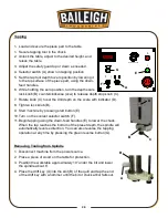
1. Load and secure the piece part to the table.
2. Secure drill bit in the chuck.
3. Unlock the table, adjust to the desired height, and
relock the table.
4. Adjust the safety guard up or down as needed.
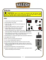
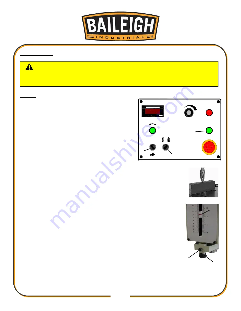
5. Select drilling mode with selector switch (A).
Selector switch (A) shown in tap position.
6. Set the drill bit depth to zero position by lowering it
to the top surface of the piece part, using the down-feed handles.
7. While holding the zero position, turn the depth scale lock knob (B)
counterclockwise (ccw) to release depth stop knob (C).
8. Rotate Knob (C) to set the drill depth on the scale with indicator (D).
9. Re-tighten lock knob (B).
10. Start machine by pressing start button (E).
11. Turn on the coolant selector switch (F).
12. Begin drilling using the down-feed handles to lower the chuck.
13. When the desired depth has been reached, return the down feed
handle to the up position. Do Not allow the handle to spin free back
to the up position.
14. Press the Red Stop button to stop the drill motor.
15. Wait for the spindle to come to a full stop before opening the chuck
guard and reaching into the drill area.
CAUTION:
Always wear proper eye protection with side shields, safety
footwear, and leather gloves to protect from burrs and sharp edges. When handling
large heavy materials make sure they are properly supported.
C
B
D
E
A
F
DIGITAL INDICATOR
RPM
0
l
150-3000RPM
0
l
SPINDLE SPEED
Содержание DP-1000VS
Страница 19: ...16 16 OVERALL DIMENSIONS ...
Страница 20: ...17 17 GETTING TO KNOW YOUR MACHINE Q F P J B C A G H I L M E F D N O K R ...
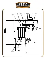
Страница 35: ...32 32 A6 2 A6 3 A6 1 A6 4 A8 1 A8 2 A5 A5 1 A33 1 A19 1 A33 ...
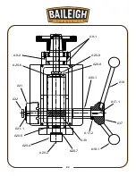
Страница 36: ...33 33 A20 7 A30 A17 2 A17 1 A17 A18 A18 1 A30 1 A20 9 A20 8 A9 1 A9 2 A20 6 A31 A32 A31 1 A20 5 A20 4 A20 2 ...
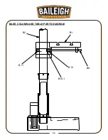
Страница 39: ...36 36 BASE COLUMN AND TABLE PARTS DIAGRAM B1 B2 B11 B10 B9 B10 1 ...
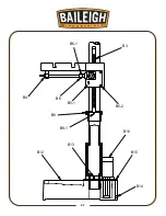
Страница 40: ...37 37 B3 B4 B6 1 B6 B5 1 B5 2 B8 B8 1 B12 B13 B16 B15 B14 ...
Страница 44: ...41 41 COOLANT PUMP ASSEMBLY PARTS DIAGRAM ...
Страница 46: ...43 43 CONTROL PANEL PARTS DIAGRAM ...
Страница 48: ...45 45 CHUCK GUARD PART DIAGRAM ...
Страница 51: ...48 48 ELECTRICAL ENCLOSURE COMPONENTS ...