


20
20
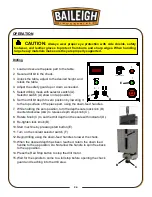
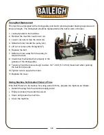
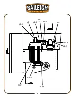
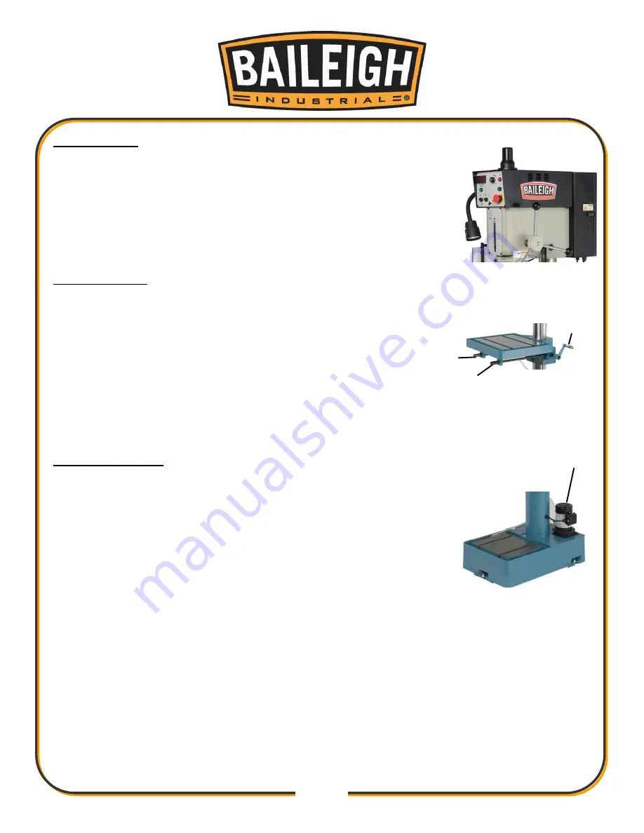
The Drill Head
The drill head attaches to the top of the column. It houses the motor,
spindle, controls, and transfer mechanisms. Attached to it is the
electrical enclosure, the protective guard, the work light, and the
coolant valve with nozzle.
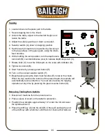
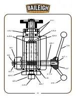
The Work Table
The sturdy work table can be positioned at varying heights and
rotated 180° in either direction. It has T-slots to allow the use of
1/2” or M14 bolts. Below the work table are three crankshafts. The
two crankshafts (F) control the up /down motion of the table.
Always unlock the table with crankshaft (I) before changing the
height or rotating it. Then lock the work table to secure in position.
The one handle works for all three crankshafts.
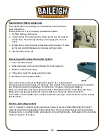
The Machine Base
The machine base houses the coolant reservoir and supports the
coolant pump (G). The coolant is pumped up to a nozzle where a valve
controls the flow onto the tool. The coolant / lubricant enters the table
drain and flows back to the reservoir.
F
F
I
G
Содержание DP-1000VS
Страница 19: ...16 16 OVERALL DIMENSIONS ...
Страница 20: ...17 17 GETTING TO KNOW YOUR MACHINE Q F P J B C A G H I L M E F D N O K R ...
Страница 35: ...32 32 A6 2 A6 3 A6 1 A6 4 A8 1 A8 2 A5 A5 1 A33 1 A19 1 A33 ...
Страница 36: ...33 33 A20 7 A30 A17 2 A17 1 A17 A18 A18 1 A30 1 A20 9 A20 8 A9 1 A9 2 A20 6 A31 A32 A31 1 A20 5 A20 4 A20 2 ...
Страница 39: ...36 36 BASE COLUMN AND TABLE PARTS DIAGRAM B1 B2 B11 B10 B9 B10 1 ...
Страница 40: ...37 37 B3 B4 B6 1 B6 B5 1 B5 2 B8 B8 1 B12 B13 B16 B15 B14 ...
Страница 44: ...41 41 COOLANT PUMP ASSEMBLY PARTS DIAGRAM ...
Страница 46: ...43 43 CONTROL PANEL PARTS DIAGRAM ...
Страница 48: ...45 45 CHUCK GUARD PART DIAGRAM ...
Страница 51: ...48 48 ELECTRICAL ENCLOSURE COMPONENTS ...